Horizontally-opposed cylindrical cam engine

A cylindrical cam, horizontally opposed technology, applied in the direction of machines/engines, cams, mechanical equipment, etc., can solve the problems of sudden changes in speed, large volume, etc., and achieve the effects of extended life, reduced volume, and good power output stability

Inactive Publication Date: 2016-09-28
ZHEJIANG UNIV
View PDF8 Cites 2 Cited by
  • Summary
  • Abstract
  • Description
  • Claims
  • Application Information

AI Technical Summary

Problems solved by technology

[0004] In order to overcome the shortcomings of the existing internal combustion engine piston connecting rod mechanism, such as the sudden change in speed at the top and bottom dead centers, the alternating side pressure during operation, and the complicated and large internal combustion engine structure, the present invention adopts a brand new internal combustion engine power transmission system.

Method used


Image

  • Horizontally-opposed cylindrical cam engine

Examples


Embodiment Construction

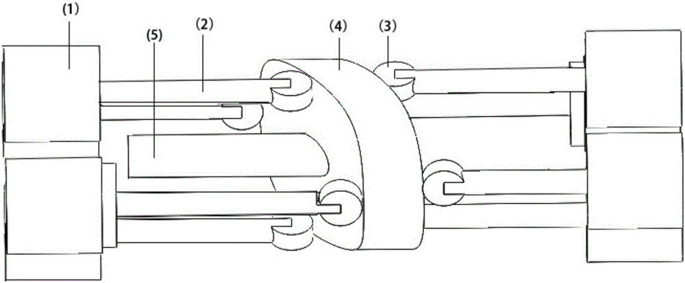
[0021] A horizontally opposed cylindrical cam 4 engine, comprising a horizontally placed cylindrical cam 4, the contour lines of the left and right end surfaces of the cylindrical cam 4 are laterally undulating curves, and a power shaft 5 is fixed in the center of the cylindrical cam 4; the left and right sides of the cylindrical cam 4 Four pistons 1 with push rods 2 are respectively arranged on each end face, and the bottom end of said piston 1 push rod 2 is provided with a roller 3, and the roller 3 moves along the contour line of the cylindrical cam 4 end face, and the piston 1 push rod The linear reciprocating motion of 2 is converted into the rotary motion of cylindrical cam 4. The four pistons 1 on one side of the cylindrical cam 4 are symmetrically arranged around the center of the cylindrical cam 4, and the rollers 3 each have a quarter phase difference on the contour line of the end face of the cylindrical cam 4. The pistons 1 on both sides of the cylindrical cam 4 ar...


PUM


Abstract

The invention relates to internal combustion engine devices, in particular to power transmission systems of internal combustion engines, and specifically relates to a horizontally-opposed cylindrical cam engine. The horizontally-opposed cylindrical cam engine comprises a cylindrical cam, wherein contour lines of the left and right end faces of the cylindrical cam are transverse curves; a power shaft is fixed in the center of the cylindrical cam; four pistons with push rods are arranged on each of the left and right end faces of the cylindrical cam; rollers are arranged at the bottom ends of the push rods of the pistons; the rollers move along the contour lines of the end faces of the cylindrical cam; and the linear back-and-forth movement of the push rods of the pistons is converted into the rotational motion of the cylindrical cam. According to the horizontally-opposed cylindrical cam engine, the contour lines are designed as cosine curves, so that the continuous change of a roller acceleration curve is achieved, namely, the rollers do not have sudden impact at upper and lower dead points; and the linear motion of the rollers is converted into the rotational motion of the cam according to the self characteristic of the cam, so that the power conversion from the reciprocating rectilinear movement of the pistons to the rotational motion is achieved, and the horizontally-opposed cylindrical cam engine has good power output stability.

Description

technical field [0001] The invention relates to an internal combustion engine device, in particular to a power transmission system of the internal combustion engine, in particular to a horizontally opposed cylindrical cam engine. Background technique [0002] The internal combustion engine mixes fuel and air and burns it in its cylinder, and the heat energy released makes the cylinder generate high-temperature and high-pressure gas. The expansion of the gas pushes the piston to do work, and then the mechanical work is output through the push rod mechanism or other mechanisms to drive the driven machine to work. [0003] At present, there are still many deficiencies in the internal combustion engine. First, there is a sudden change in the speed direction of the piston of the engine when it is at the top and bottom dead centers. Alternating side pressure seriously affects the service life of push rods and pistons; finally, the existing engine structure is cumbersome and bulky...

Claims


Application Information

Patent Timeline
IPC IPC(8): F02B75/18F02B75/24F16H53/08
CPCF02B75/18F02B75/24F02B2075/1832F16H53/08
Inventor 许印川熊树生郭越王宇杨兴浩万波申恩恩王亚彬滕志峰李康
Owner ZHEJIANG UNIV
Why Eureka
Try Eureka