
Temperature and pressure automatically-balanced spectrograph device and method for measuring oil and gas components while drilling

A measurement method and spectrometer technology, applied in measurement devices, measurement, instruments, etc., can solve the problems of inability to conduct real-time online analysis of oil and gas components, high cost of quantum cascade lasers, and inability to meet high temperature environments, and achieve a wide natural operating temperature range. , huge practical value, low power consumption effect

Pending Publication Date: 2016-09-28
CHINA UNIV OF PETROLEUM (EAST CHINA)
View PDF4 Cites 9 Cited by
  • Summary
  • Abstract
  • Description
  • Claims
  • Application Information

AI Technical Summary

Problems solved by technology

[0004] 1. None of the above methods can achieve detection while drilling
[0005] 2. The above method cannot perform real-time online analysis of oil and gas components
[0007] 1. There are many peripheral supporting equipment and the cross section is large
[0008] 2. Quantum cascade lasers have high cost and high power consumption
[0009] 3. Quantum cascade lasers generally use a far-infrared light source with a wavelength of 5um or more, and the Raman scattering generated is a far-infrared signal with a longer wavelength, which is difficult to detect by the optical system
[0010] Laser-based spectroscopy technology can measure accurately and quickly, but the maximum operating temperature of the light source laser diodes and detectors used in the near-infrared and mid-infrared bands is 60-80°C, which cannot meet the high-temperature environment of detection-while-drilling

Method used


Image

  • Temperature and pressure automatically-balanced spectrograph device and method for measuring oil and gas components while drilling
  • Temperature and pressure automatically-balanced spectrograph device and method for measuring oil and gas components while drilling
  • Temperature and pressure automatically-balanced spectrograph device and method for measuring oil and gas components while drilling

Examples


Embodiment Construction

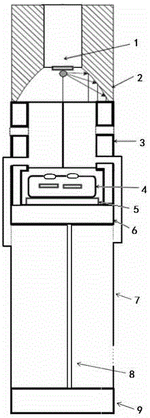
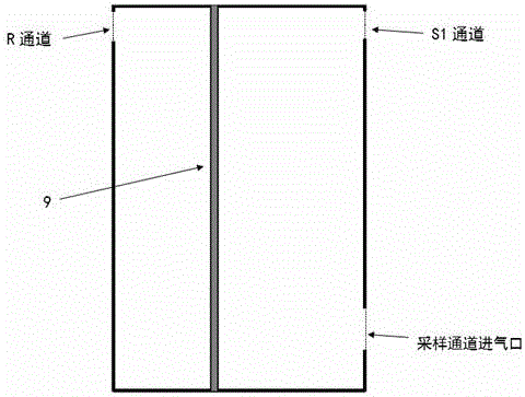
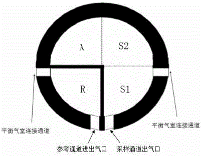
[0045] Accompanying drawing is a kind of specific embodiment of the present invention. This embodiment includes a parabolic reflector 2 for collimating the light-emitting point of the light source 1. The light source 1 is installed in the parabolic reflector 2, and its light-emitting point is located at the focus of the parabolic reflector 2, and the emitted light is emitted in parallel to achieve collimation. The chamber body 3 of the gas chamber is connected with the parabolic reflector 2, the balance gas chamber 7 and the mounting bases 6, 9 in sealing connection, and the two ends of the gas channel are equipped with projection windows for sealing design. There are four channels in the cavity 3 of the sampling gas chamber and the reference gas chamber, and the reference channel and the sampling channel communicate with both sides of the balance gas chamber 7 to ensure that the pressures of the connected channels are the same. The detector 4 has four channels and four indepe...


PUM

PropertyMeasurementUnit
diameteraaaaaaaaaa
diameteraaaaaaaaaa
lengthaaaaaaaaaa

Abstract

The invention relates to a temperature and pressure automatically-balanced spectrograph device and method for measuring oil and gas components while drilling. The device comprises a parabolic reflector for collimating a light source and is characterized in that a sampling air chamber, a reference air chamber, a detector with four independent thermoelectricity units and temperature sensors, and a balance air chamber capable of automatically balancing the pressure of the reference air chamber and the pressure of the sampling air chamber are sequentially arranged below the reflector. A sliding piston is arranged in the balance air chamber. The device has the advantages that the analysis speed is high, and an analysis task can be completed within 5 s; the analysis cost is low, and no sample is consumed in the analysis process; real-time online analysis can be carried out, a detection analysis result can be transmitted to the ground in real time, the practical value is huge, and oil and gas field detection efficiency is improved; hydrogen sulfide qualitative detection is achieved besides oil and gas detection, the operation safety is increased, and the device is resistance to high pressure and temperature, small in size, low in power consumption and capable of being conveniently integrated into the equipment operated during drilling.

Description

(1) Technical field [0001] The invention relates to a spectrometer-while-drilling system, in particular to a measuring method and device for a spectrometer-while-drilling system for measuring oil and gas components with temperature and pressure self-balancing. (2) Background technology [0002] In the process of developing oil and gas reservoirs, the detection of oil and gas components mainly focuses on two links of mud logging and well logging. Mud logging is mainly through testing the drilling fluid, while well logging is mainly through sampling and testing the formation fluid after drilling is completed. In terms of well logging, R. DiFoggio of BakerHughes Company used the light transmission curve method to obtain two-dimensional images ranging from 400 nanometers to 2000 nanometers of the mud mixture flowing through the section of the sampling pipeline, which can visually determine whether it contains oil and gas. [0003] The disadvantages of the above method mainly li...

Claims


Application Information

Patent Timeline
Patent Type & Authority Applications(China)
IPC IPC(8): E21B47/00E21B49/08G01N21/3504G01N21/01
CPCE21B47/00E21B49/08G01N21/01G01N21/3504G01N2021/0112
Inventor 季文海潘帅好
Owner CHINA UNIV OF PETROLEUM (EAST CHINA)
Learn More