Rotary positioning machining rotary table

A turntable and processed technology, used in positioning devices, metal processing equipment, metal processing machinery parts, etc., can solve problems such as relying on horizontal processing, and achieve the effect of compact structure, easy handling and easy installation

Active Publication Date: 2016-09-28
HUBEI SANJIANG AEROSPACE WANFENG TECH DEV
View PDF8 Cites 15 Cited by
  • Summary
  • Abstract
  • Description
  • Claims
  • Application Information

AI Technical Summary

Problems solved by technology

[0004] The object of the present invention is to provide a rotary positioning processing turntable, which is especially suitable for the vertical machining center with a longer angle head to process the rotary positioning processing of the inner plane and convex table surface of the deep tube conical or deep tube cylindrical cabin section, which solves the problem of In the prior art, the processing of the inner plane of the cabin, especially the processing of the inner plane of the conical cabin can only rely on the problem of horizontal machining

Method used


Image

  • Rotary positioning machining rotary table
  • Rotary positioning machining rotary table
  • Rotary positioning machining rotary table

Examples


Embodiment Construction

[0030] The present invention will be further described below in conjunction with drawings and embodiments.

[0031] Figure 1 to Figure 5 It is an embodiment of the present invention.

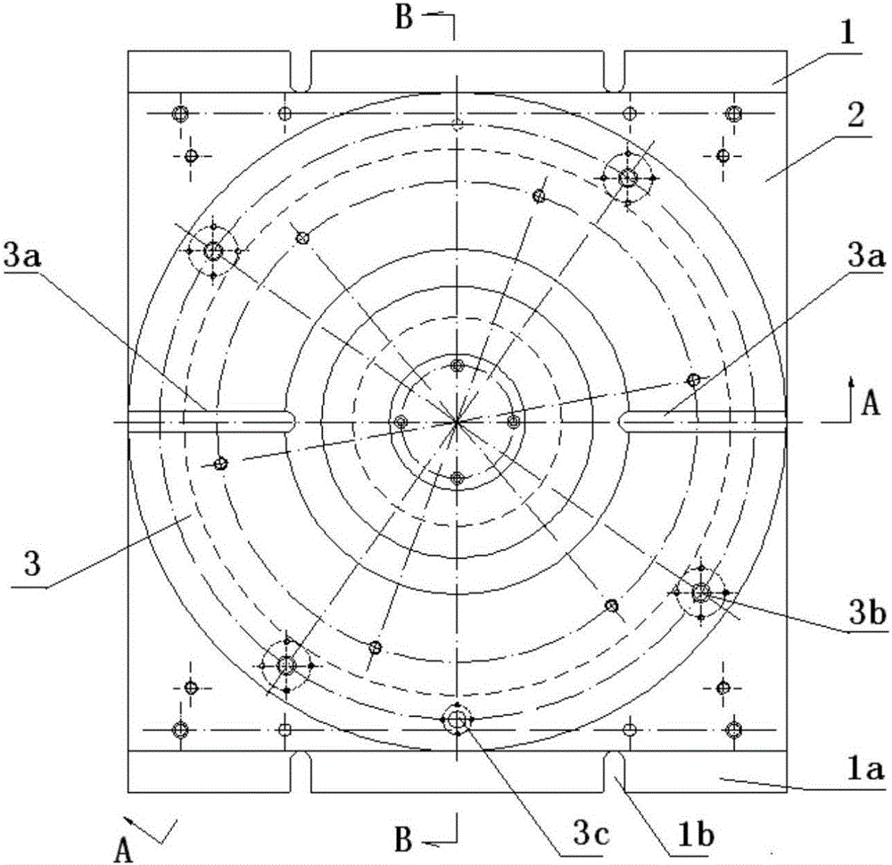
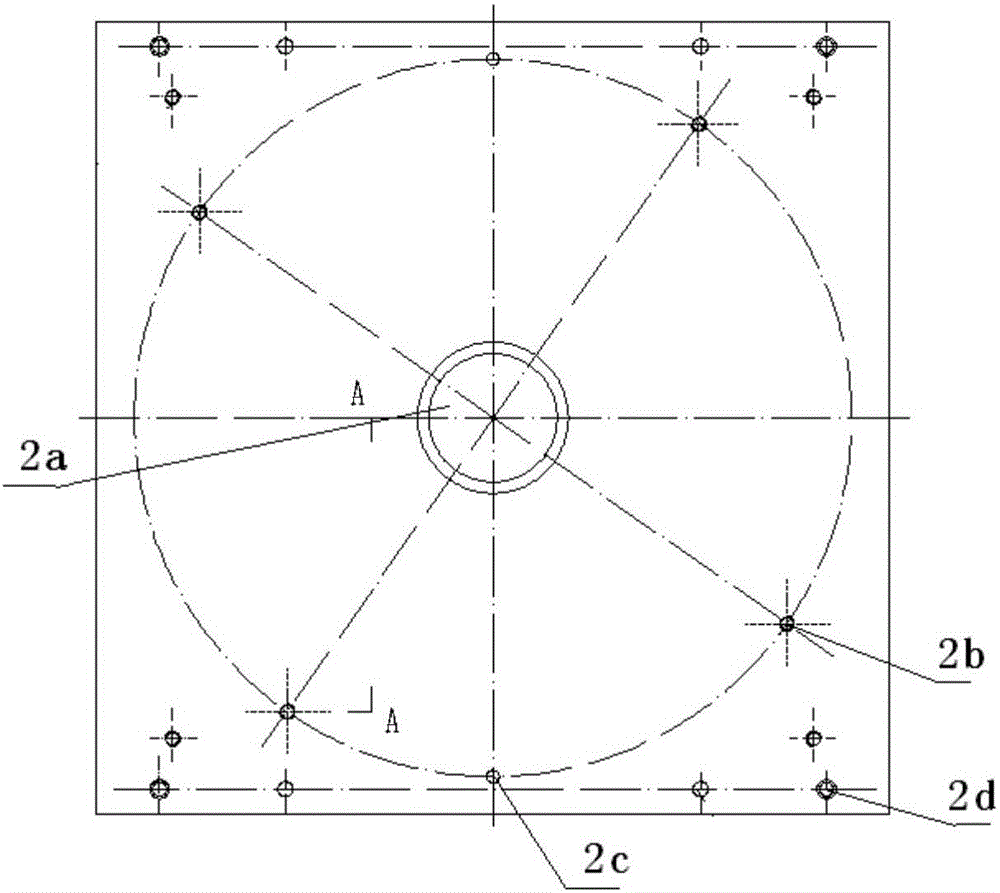
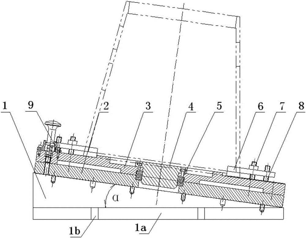
[0032] Such as figure 1 , figure 2 , image 3 , Figure 4 , Figure 5 , Figure 6 , Figure 7 As shown: the rotary positioning processing turntable of the present invention includes an angle base, a turntable, a rotating shaft, and a thrust bearing. The slope angle of the angle base 1 is equal to the included angle between the busbar of the processed conical cabin section and the axis, and the turntable bottom plate 2 is installed on the angle base 1. , the turntable 3 is connected to the rotating shaft 4 and installed on the turntable bottom plate 2 through the thrust bearing 5; the center of the turntable bottom plate 2 is provided with a bottom plate step hole 2a for installing the thrust bearing, and the periphery of the turntable bottom plate 2 is provided with evenly distributed b...


PUM


Abstract

The invention provides a rotary positioning machining rotary table comprising an angle base. The slope angle of the angle base is equal to an included angle between a bus and an axis of a machined conical cabin segment; the angle base is provided with a rotating disk bottom plate; after a rotating disk is connected with a rotating shaft, the rotating disk is installed on the rotating disk bottom plate through a thrust bearing; a bottom plate stepped hole for installing the thrust bearing is formed in the center portion of the rotating disk bottom plate; evenly-distributed bottom plate locking screw holes are formed in the periphery of the rotating disk bottom plate; positioning holes are further formed in the peripheral line of the rotating disk bottom plate; rotating disk stepped holes for installing the rotating shaft and the thrust bearing are formed in the center of the rotating disk; the positions, opposite to the bottom plate locking screw holes of the rotating disk bottom plate, on the rotating disk are provided with rotating disk locking stepped holes; a rotating disk locking assembly is installed above the rotating disk locking stepped holes; the rotating disk is further provided with a positioning pin hole which corresponds to the positioning holes in the rotating disk bottom plate; a plug pin assembly is installed above the positioning pin hole; a positioning boss is arranged on the middle portion of the rotating disk; the positioning boss is matched with a bottom hole of a machined conical cabin; and threaded rod installing screw holes are evenly distributed in the outer ring of the positioning boss on the rotating disk and used for installing a pressing plate, and the machined conical cabin is fixed.

Description

technical field [0001] The invention belongs to the technical field of non-standard special process equipment, and mainly relates to a rotary positioning processing turntable, which is mainly used for the step plane in the processing cabin section of the angle milling head of the existing processing center. Background technique [0002] At present, the company is responsible for the production of a certain type of cabin shell, which is made of aluminum alloy casting and has high requirements for internal quality and external dimension accuracy. , mouth frame and front and rear end frames, etc., with many windows, thin walls, high precision requirements (IT7-IT8 level), and many processing surfaces. Because the company currently lacks multi-axis processing machines, it often needs to go through multiple processes such as turning, milling, boring, and clamping. Repeated alignment and processing of the first process not only has a large workload, many processing procedures, lon...

Claims


Application Information

Patent Timeline
IPC IPC(8): B23Q1/26B23Q3/06
CPCB23Q1/26B23Q3/069
Inventor 邓平盛陈海军王元成朱幼芬潘龙玉龙登坛张谢民
Owner HUBEI SANJIANG AEROSPACE WANFENG TECH DEV
Why Eureka
Try Eureka