Near-infrared detector uniformity test system

A testing system and detector technology, applied in electrical radiation detectors and other directions, can solve the problems of surface condensation and frost, long continuous working time, influence of near-infrared detector uniformity test accuracy, etc., to achieve low background radiation, guarantee The effect of precision

Inactive Publication Date: 2016-09-21
HEFEI INSTITUTES OF PHYSICAL SCIENCE - CHINESE ACAD OF SCI
View PDF4 Cites 5 Cited by
  • Summary
  • Abstract
  • Description
  • Claims
  • Application Information

AI Technical Summary

Problems solved by technology

[0003] The dark current level of the near-infrared detector is directly related to the operating temperature. The lower the operating temperature, the lower the dark current level. Therefore, the uniformity test of the near-infrared detector should also ensure that it works in a certain low temperature environment; at the same time, the near-infrared detector The temperature difference between the low-temperature working temperature of the infrared detector and the test environment will cause dew and frost on the surface; the test light source is a general-purpose integrating sphere, but the light emitted by the integrating sphere at a large angle will be reflected multiple times in the test light-proof box to form an abnormal Stray light in the normal optical path affects the accuracy of the near-infrared detector uniformity test; due to the fact that the near-infrared detector is greatly affected by background radiation at room temperature, certain measures must be taken to suppress the background radiation during the test ; The uniformity test of the near-infrared detector requires data collection for the response of different cooling temperatures and different integration times. Its continuous working time is long and requires a stable low-temperature working environment

Method used


Image

  • Near-infrared detector uniformity test system
  • Near-infrared detector uniformity test system

Examples


Embodiment Construction

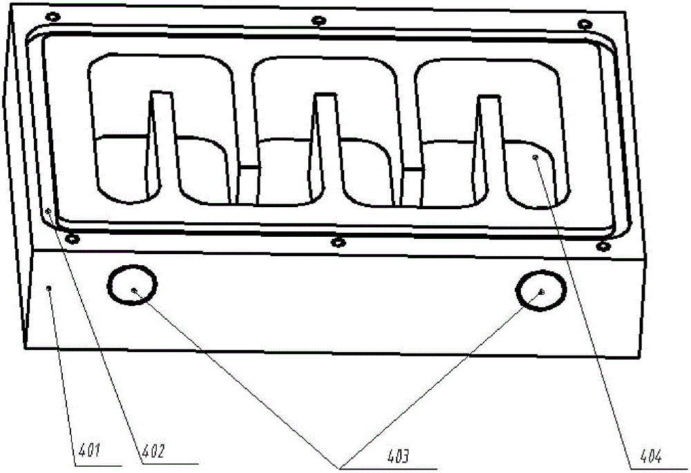
[0026] Such as figure 1 , figure 2 As shown, a near-infrared detector uniformity test system includes an integrating sphere 1, a light-proof box 2, a cold screen 3, a heat exchanger 4, a near-infrared detector 5, a lifting platform 6, a hose 7, and a circulating liquid Refrigerator 8 and nitrogen charging equipment 9. A cold screen 3 and a near-infrared detector 5 are sequentially arranged in the light-proof box 1 along the light path. The cold screen 3 and the near-infrared detector 5 are all placed on the heat exchanger 4, and the heat exchanger 4 is installed on the lifting platform 6. The height can be adjusted. Adjustment, the integrating sphere 1 is at the same height as the cold screen 3 and the near-infrared detector 5 along the optical path, the circulating liquid refrigerator 8 and the hose 7, and the nitrogen filling equipment 9 are outside the light-proof box 2, and the circulating liquid refrigerator 8 passes through the hose 7 is connected with the outlet of t...


PUM


Abstract

The present invention discloses a near-infrared detector uniformity test system. The system comprises a light avoiding box holding a near infrared detector to be tested; an integrating sphere is arranged at the opening of the front end of the light avoiding box; the light avoiding box is internally provided with a cold shield located on the emitting light path of the integrating sphere to the near infrared detector to be tested and internally provided with a heat exchanger for supporting the near infrared detector and the cold shield and a lifting platform for supporting the heat exchanger; a cycle liquid refrigerating machine and a filling nitrogen device are arranged at the outside of the light avoiding box; the cycle liquid refrigerating machine and the filling nitrogen device are connected with the heat exchanger to form a circulation pipeline; and the filling nitrogen device lets the nitrogen in the light avoiding box through the pipeline. The near-infrared detector uniformity test system provides stable low-temperature, low-background radiation and drying test environment and test state for the uniformity test of the near infrared detector.

Description

technical field [0001] The invention relates to the field of optical system testing, in particular to a near-infrared detector uniformity testing system. Background technique [0002] The near-infrared detector uniformity test refers to the test of the inconsistency of the output signal of each pixel due to the differences in response, noise level and quantum efficiency among the pixels under the same lighting conditions. The uniformity test of near-infrared detectors provides an important basis for the calibration of near-infrared detectors and the image quality of photoelectric instruments. With the improvement of image quality requirements of optoelectronic instruments and users, it is urgent to conduct high-precision and high-stability uniformity testing for near-infrared detectors to meet subsequent image processing and correction. [0003] The dark current level of the near-infrared detector is directly related to the operating temperature. The lower the operating tem...

Claims


Application Information

Patent Timeline
Patent Type & Authority Applications(China)
IPC IPC(8): G01J5/10
CPCG01J5/10
Inventor 徐标陈迪虎罗海燕李志伟熊伟崔珊珊
Owner HEFEI INSTITUTES OF PHYSICAL SCIENCE - CHINESE ACAD OF SCI
Why Eureka
Try Eureka