Prefabricated shear wall reinforcement cage component, column reinforcement cage component and manufacturing and assembling method

A steel cage and shear wall technology, applied in building components, building structures, walls, etc., can solve the problems of difficult construction, heavy PC components, and high cost, reducing high-altitude operations, simplifying installation procedures, and reducing transportation. cost effect

Active Publication Date: 2018-09-21
SOUTHEAST UNIV
View PDF5 Cites 0 Cited by
  • Summary
  • Abstract
  • Description
  • Claims
  • Application Information

AI Technical Summary

Problems solved by technology

In order to meet the connection strength requirements of precast concrete components, the reinforcement of the connection nodes is complex and dense, the manual work space is very cramped, the construction is difficult, and the quality and strength of the steel connection are difficult to guarantee, which in turn affects the overall strength and stability of the reinforced concrete structure.
[0005] Existing PC components (full prefabricated reinforced concrete components) are heavy, difficult to transfer, hoist, and locate, and temporary auxiliary support facilities need to be built on site; during the assembly process, the vertical nodes need to be connected by grout anchors, which requires high technical requirements and requires grouting construction techniques. and quality control measures are complex; horizontal joints need to be connected by formwork support cast-in-place, pre-embedded steel plate welding, high-strength bolt connection, etc. The process is complicated, the cost is high, and the reliability is poor. It can only be used after expert argumentation or appraisal organized by relevant departments

Method used


Image

  • Prefabricated shear wall reinforcement cage component, column reinforcement cage component and manufacturing and assembling method
  • Prefabricated shear wall reinforcement cage component, column reinforcement cage component and manufacturing and assembling method
  • Prefabricated shear wall reinforcement cage component, column reinforcement cage component and manufacturing and assembling method

Examples


Embodiment Construction

[0050] The present invention will be further described below in conjunction with embodiment and accompanying drawing.

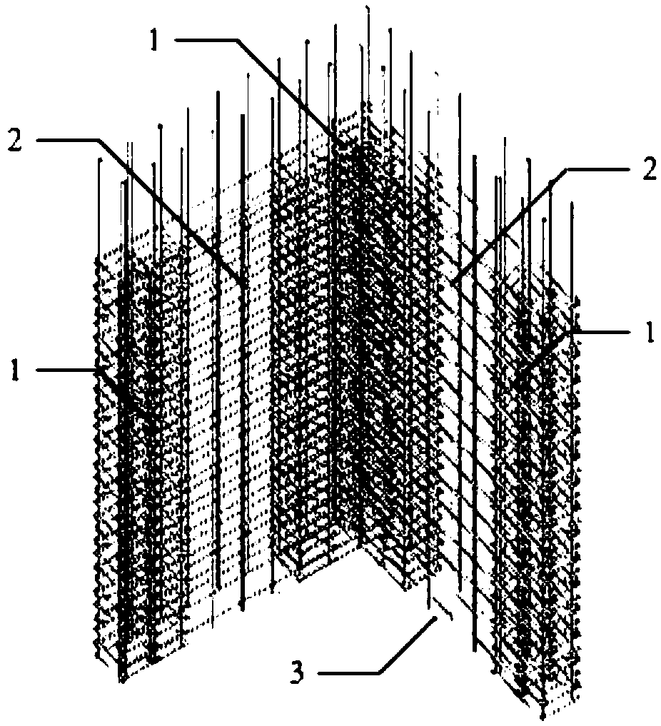
[0051] The prefabricated shear wall reinforcement cage member of the present invention is a straight, T-shaped, L-shaped, H-shaped or Z-shaped structure, including a plurality of prefabricated edge restraint members 1, and steel mesh sheets connected with the prefabricated edge restraint members 1 2 and installation of the free formwork 3 arranged on the outside of the steel mesh 2, each prefabricated edge restraint member 1 is set independently, the steel mesh 2 is arranged along the wall of the shear wall, and all the prefabricated edge restraint members 1 are connected Assembled together, the demolition-free formwork 3 is integrated with the reinforcement mesh sheet 2 through positioning fixtures. Among them, the demolition-free formwork 3 adopts a demolition-free net mold or a demolition-free formwork.

[0052] In one embodiment, the prefabricated edge c...


PUM


Abstract

The invention discloses a prefabricated shear wall reinforcement cage member and column reinforcement cage member as well as manufacturing and assembling methods thereof. The prefabricated shear wall reinforcement cage member comprises a plurality of prefabricated edge restraining members, a reinforcement mesh connected with the prefabricated edge restraining members and a dismantling-free mold mounted outside the reinforcement mesh; the reinforcement mesh is arranged along a wall surface of a shear wall; all the prefabricated edge restraining members are connected together; a dismantling-free mesh is integrally connected with the reinforcement mesh through a positioning fastener. According to the invention, the super-large member assembly and reinforced concrete large-structure space civil construction, which cannot be completed by existing members and processes, can be realized; the working procedure is simplified; the high-altitude work is reduced; the transfer cost is reduced; the efficiency is improved; the on-site positioning is convenient; the process is controllable.

Description

technical field [0001] The invention belongs to the field of construction engineering and relates to a prefabricated shear wall component, a prefabricated column component and an assembly method. Background technique [0002] Reinforced concrete structures are widely used due to their advantages of integrity, durability, fire resistance and seismic performance. The existing reinforced concrete structure mainly includes erecting formwork on the construction site, configuring steel bars, pouring and tamping concrete to form an integral reinforced concrete structure, and adopting prefabricated reinforced concrete components at the factory or construction site, and assembling them at the site. The overall reinforced concrete structure. Both methods involve the configuration of steel reinforcement inside the structure or component, and the existing reinforcement technology is mainly divided into two types: [0003] One is that after the formwork is erected on site, the workers ...

Claims


Application Information

Patent Timeline
Patent Type & Authority Patents(China)
IPC IPC(8): E04C5/06E04B2/84E02D5/20
CPCE02D5/20E04B2/845E04C5/06E04C5/0609E04C5/064
Inventor 张宏张军军刘子洁刘春刘盾吴京冯世虎
Owner SOUTHEAST UNIV
Why Eureka
Try Eureka