Gear subjected to surface treatment process
A surface treatment and gear technology, applied in the direction of belts/chains/gears, components with teeth, hoisting devices, etc., can solve the problems of costing materials, not solving gear wear, energy consumption, etc.
- Summary
- Abstract
- Description
- Claims
- Application Information
AI Technical Summary
Problems solved by technology
Method used
Image


Examples
Embodiment 1
[0046] A method for coating a wear-resistant high-strength resin coating on the surface of a gear: comprising the following steps:
[0047] Step 1: Fix the gear to be coated in the mold 40; wherein the inner axis of the mold 40 is provided with a hole for installing the gear, so that when the gear is fixed at a predetermined axial fixed position, it corresponds to a coating resin thickness of 0.3 mm. Cavity 41; 4 through holes are provided on one side of the mold where the resin is injected. When the mold 40 is closed, the shaft passes through the through hole in the center of the mold side of the gear and the injection resin, and there are 3 cylindrical pins on the mold on the side of the fixed gear, and the pins pass through 3 of the periphery of the mold side of the injection resin. Through the hole, the gear is embedded in the mold. Three injection ports are provided in the middle of the above three through holes for injecting molten wear-resistant high-strength resin. Th...
Embodiment 2
[0054] Before the gear surface is coated with the wear-resistant high-strength resin coating, nitric acid or mixed acid is used to corrode the gear tooth surface to increase the adhesion between the gear surface and the wear-resistant high-strength resin coating.
[0055] Described mixed acid comprises:
[0056] A method for coating a wear-resistant high-strength resin coating on the surface of a gear: comprising the following steps:
[0057] Step 1: Fix the gear to be coated in the mold; wherein the mold is provided with a shaft for installing the gear, so that when the gear is fixed at a predetermined axial fixed position, it corresponds to a mold cavity with a coating resin thickness of 20mm; when injecting the resin There are 4 through holes on one side of the mold. When the mold is closed, the shaft passes through the through hole in the center of the gear and the side of the mold where the resin is injected, and there are 3 cylindrical pins on the mold on the side of th...
Embodiment 3
[0063] Such as figure 1 As shown in , the present invention also shows positioning and processing equipment for preheating and surface treatment of the gear 10 .
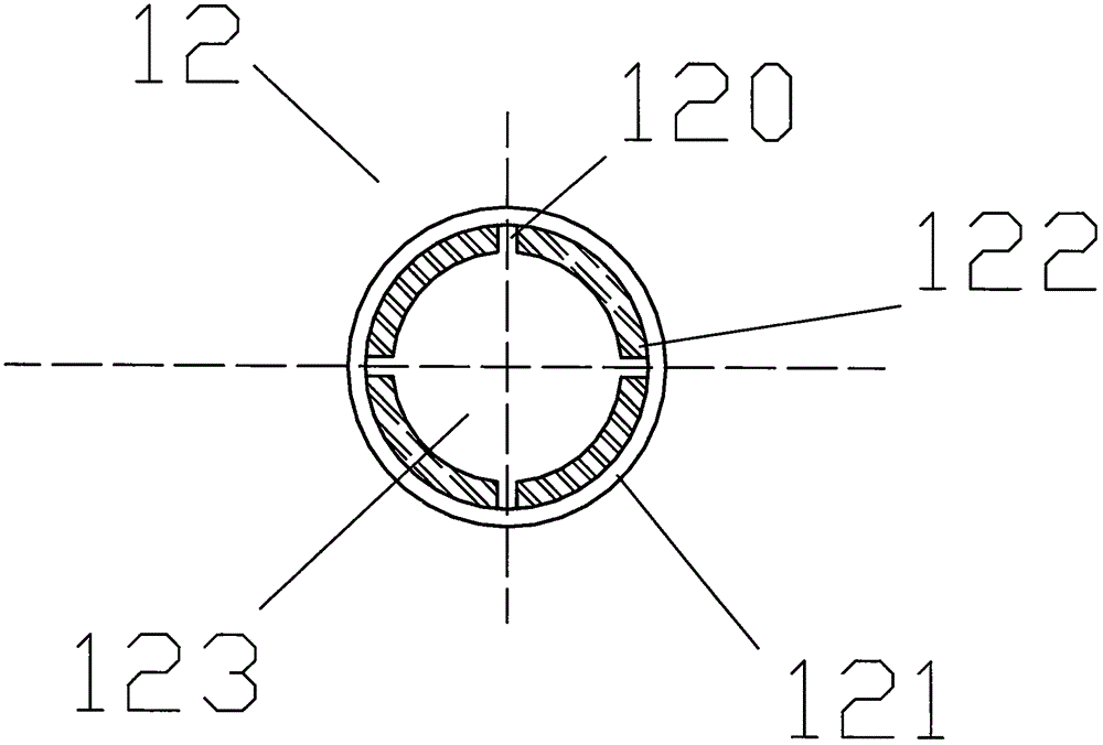
[0064] In this case, for the sake of clarity, the dies arranged outside the gear wheel 10 are not shown in the figure. The gear 10 includes a gear main body 11 and an intermediate hub 12 . The external teeth of the gear may typically have straight teeth. The two middle hub parts 12 located on the sides of the gear 10 extend from the center shaft of the gear in opposite directions to the two sides.
[0065] The apparatus includes a frame 100 (the remainder not shown) on which the molds can be fixed, and the frame 100 can obviously also include other frames (not shown) extending upwards to accommodate or hold the molds and other injection-needed components. equipment.
[0066] In particular, the rack 100 includes a positioning head 14 at the lower part of the rack operating table, the positioning head 14 is rotat...
PUM
 Abstract
Description
Claims
Application Information
 - R&D
- Intellectual Property
- Life Sciences
- Materials
- Tech Scout
- Unparalleled Data Quality
- Higher Quality Content
- 60% Fewer Hallucinations
Browse by: Latest US Patents, China's latest patents, Technical Efficacy Thesaurus, Application Domain, Technology Topic, Popular Technical Reports.
© 2025 PatSnap. All rights reserved.Legal|Privacy policy|Modern Slavery Act Transparency Statement|Sitemap|About US| Contact US: help@patsnap.com