
Inertia piezoelectric driver

A piezoelectric driver, inertial technology, applied in the direction of generator/motor, piezoelectric effect/electrostrictive or magnetostrictive motor, electrical components, etc., can solve the complex structure and poor applicability of miniature piezoelectric driver. question

Active Publication Date: 2016-08-31
谐振机电精密技术(苏州)有限公司
View PDF6 Cites 6 Cited by
  • Summary
  • Abstract
  • Description
  • Claims
  • Application Information

AI Technical Summary

Problems solved by technology

[0003] In order to solve the problems of complex structure and poor applicability of the current micro piezoelectric actuator, an inertial piezoelectric actuator is proposed. The actuator is composed of a piezoelectric vibrator, a mass block, a base and a composite cantilever. The block vibrates, using inertial forces to orient the entire drive

Method used


Image

  • Inertia piezoelectric driver
  • Inertia piezoelectric driver
  • Inertia piezoelectric driver

Examples


Embodiment Construction

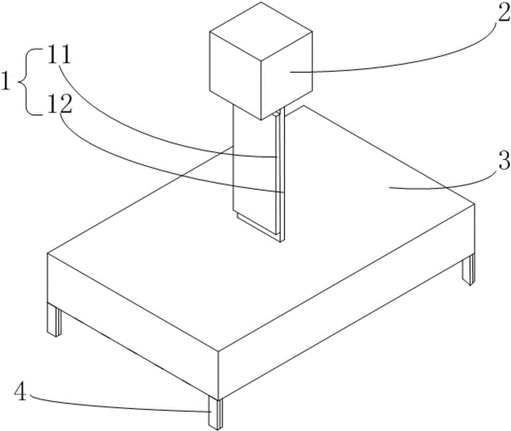
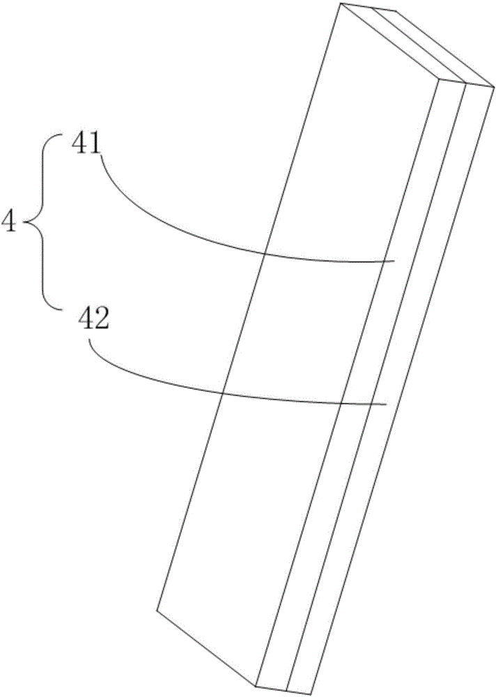
[0011] refer to figure 1 and figure 2 , an inertial piezoelectric actuator of the present invention, comprising a piezoelectric vibrator 1, a mass block 2 and a base 3, characterized in that it also includes a composite cantilever 4, wherein: the two ends of the piezoelectric vibrator 1 are respectively fixedly connected to the mass on the block 2 and the base 3; the composite cantilever 4 is a thin sheet structure and is composed of a high-friction elastic material 41 and a low-friction elastic material 42, and the high-friction elastic material 41 and the low-friction elastic material 42 are sheet-type structures and have the same size. The friction coefficient of the high-friction elastic material 41 is greater than that of the low-friction elastic material 42. The four composite cantilevers 4 are arranged on the lower surface of the base 3, and all of them The low-friction elastic material 42 faces the same side; the piezoelectric vibrator 1 is formed by bonding the pie...


PUM


Abstract

The invention relates to an inertia piezoelectric driver. The inertia piezoelectric driver comprises a piezoelectric oscillator, a mass block, a base and composite cantilevers. Two ends of the piezoelectric oscillator are respectively and fixedly connected with the mass block and the base. The composite cantilevers are of a thin sheet structure and are respectively formed by lamination of a high friction elastic material and a low friction elastic material. The friction coefficient of the high friction elastic material is larger than that of the low friction elastic material. The four composite cantilevers are arranged on the lower surface of the base. The bonding surface between a piezoelectric ceramic and an elastic substrate is perpendicular to the upper surface of the base. The intersection line between the elastic substrate and the upper surface of the substrate is parallel to the lamination surface of the high friction elastic material and the low friction elastic material. The inertia force and two different friction coefficients of the composite cantilevers are utilized to enable the driver to move upwards. As a simple piezoelectric driving device, the inertia piezoelectric driver can be applied to the fields of software robots, detection and rescue, and biomedical treatment, and the inertia piezoelectric driver has the advantages that the structure is simple, the size is small and the applicability is high.

Description

technical field [0001] The invention belongs to the field of piezoelectric driving, and in particular relates to an inertial piezoelectric driver. Background technique [0002] With the development of science and technology, micro-drive technology occupies an increasingly important position in the fields of ultra-precision machinery and its manufacturing, precision measurement, biomedicine and other disciplines, and micro-drives are also receiving more and more attention in civilian applications. Piezoelectric ceramic materials have the advantages of high precision, fast response, low driving power, wide operating frequency, and immunity to electromagnetic interference. Therefore, in recent years, precision drivers using such components as driving sources have developed rapidly. However, the existing piezoelectric micro-actuators have a relatively complex structure, difficult processing, high cost, and most of them are rigid structures. When working, the driver is directly i...

Claims


Application Information

Patent Timeline
Patent Type & Authority Applications(China)
IPC IPC(8): H02N2/02H02N2/04H02N2/06
CPCH02N2/0015H02N2/006H02N2/0065H02N2/007H02N2/02H02N2/04H02N2/062
Inventor 吴越杨志刚刘庆萍王京春王旭宋正义
Owner 谐振机电精密技术(苏州)有限公司
Learn More