
Suspension type wireless charging system of electric bus platform

An electric bus and wireless charging technology, applied in electric vehicle charging technology, electric vehicles, charging stations for charging mobile devices, etc., can solve the problem of short battery life of large-capacity battery packs, increased difficulty in shielding system design, and reduced bus operation Efficiency and other issues to achieve the effect of enhancing power transmission capacity, no fire hazards, and cost savings

Active Publication Date: 2016-08-24
SHANGHAI ZHONGLIAN NENGCHUANG NEW ENERGY TECH CO LTD
View PDF5 Cites 31 Cited by
  • Summary
  • Abstract
  • Description
  • Claims
  • Application Information

AI Technical Summary

Problems solved by technology

In addition, wireless charging cannot solve the problem of electric buses' need for large-capacity battery packs and short battery life
[0007] To sum up, the disadvantages of electric bus charging include: 1. The battery has a large volume and weight, which reduces the operating efficiency of the bus
2. Short battery life
For the wireless charging of electric buses, its disadvantages include: 1. The transmission distance between the ground and the chassis is large, and the transmission efficiency is low; 2. Metal objects on the ground have fire hazards; 3. A metal detection device needs to be designed separately, and the cost is high; 4. The space under the vehicle is limited, and the design of the electromagnetic field shielding system is more difficult

Method used


Image

  • Suspension type wireless charging system of electric bus platform
  • Suspension type wireless charging system of electric bus platform
  • Suspension type wireless charging system of electric bus platform

Examples


Embodiment Construction

[0037] In order to make the purpose, technical solutions and advantages of the embodiments of the present invention more clear, the technical solutions in the embodiments of the present invention will be clearly and completely described below in conjunction with the drawings in the embodiments of the present invention. The following examples are only used to illustrate the technical solution of the present invention more clearly, but not to limit the protection scope of the present invention.

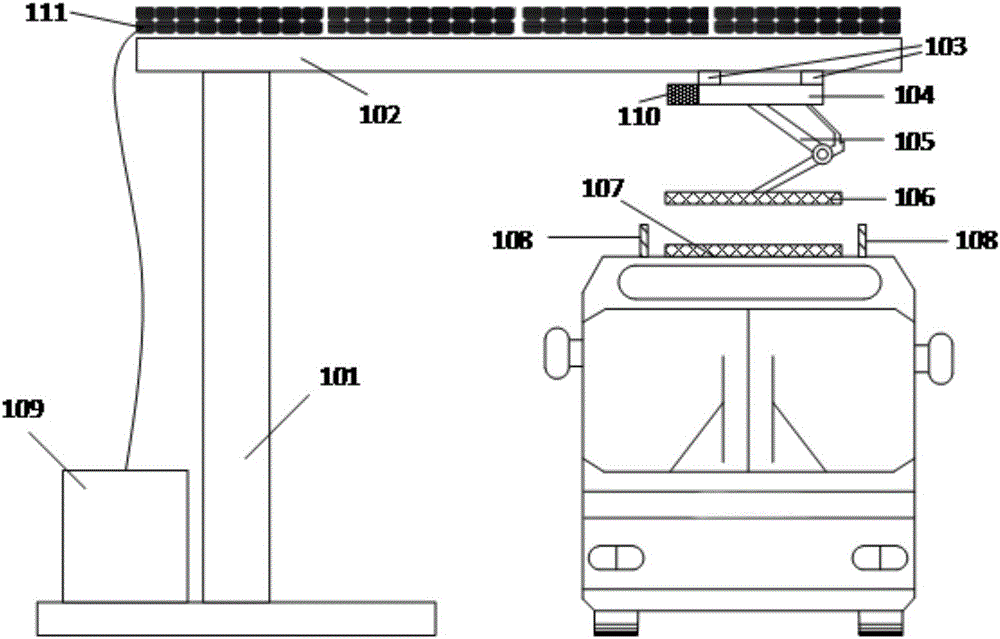
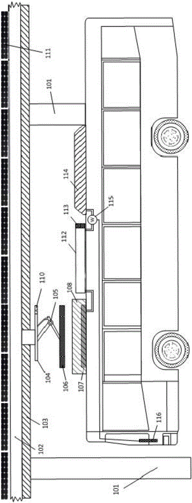
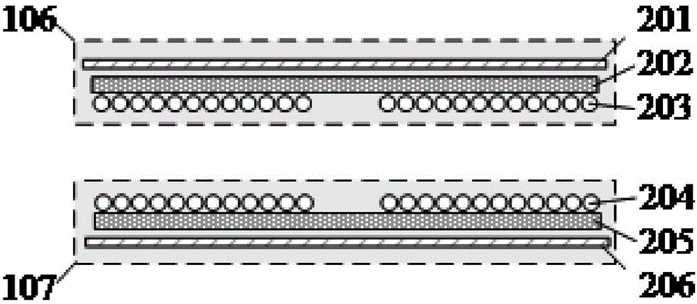
[0038] figure 1 and figure 2 A suspended wireless charging system for electric bus stops is demonstrated. The suspended wireless charging system consists of two parts: the power transmitting device on the side of the bus stop and the power receiving device on the side of the electric bus. The bus stop should have a roof 102 that extends and covers the lane where the electric bus stops. The power transmitting device of the wireless charging system is installed on the ceiling 102 of t...


PUM


Abstract

The invention discloses a suspension type wireless charging system of an electric bus platform. The suspension type wireless charging system comprises an electric energy emission device and an electric energy receiving device, wherein the electric energy emission device is arranged on the bus platform, the electric energy receiving device is arranged on an electric bus, the electric energy emission device comprises a linear motor, a position sensing adjustment system, a height adjustment arm, an emission coil, a primary electric energy adjustment device and a signal receiving processing system, and the electric energy receiving device comprises a receiving coil, a secondary electric energy adjustment device, a signal emission device, a vehicle-mounted battery pack, a vehicle-mounted display control device and a shielding device. The brand-new suspension type wireless charging system of the electric bus platform, proposed by the invention, can be used for an ordinary structural electric bus, the electric bus driving to the bus platform can be charged in a wireless way, the electric energy transmission efficiency can be effectively improved, the capacity of the battery pack is reduced, the service lifetime of a battery is prolonged, and the charging cost is greatly reduced.

Description

technical field [0001] The invention belongs to the technical field of wireless charging. More specifically, the invention relates to a suspension type wireless charging system for an electric bus platform, which can perform high-power wireless charging for an electric bus parked on the platform in a short time. technical background [0002] With the intensification of global warming, energy conservation and emission reduction has become the focus of attention around the world. Traditional fuel-powered buses can no longer meet the needs of energy conservation and emission reduction. Electric new energy buses can greatly reduce emissions or even achieve zero emissions. , which is not only conducive to energy saving and emission reduction, but also can effectively reduce operating costs. It has become the best choice for the public transportation system and has huge development potential in China. According to relevant statistics, the daily mileage of each bus in my country is...

Claims


Application Information

Patent Timeline
IPC IPC(8): H02J7/02H02J50/12H02J50/90
CPCH02J5/005H02J7/0027H02J7/025Y02T10/70Y02T10/7072Y02T90/14
Inventor 吴迪
Owner SHANGHAI ZHONGLIAN NENGCHUANG NEW ENERGY TECH CO LTD
Learn More