Slot antenna of metal via hole stepped-impedance

A step impedance, slot antenna technology, applied in slot antennas, antennas, antenna grounding devices, etc., can solve the problems of large slot impedance, antenna cross-polarization deterioration, spectral efficiency and channel capacity reduction, etc. Small electrical size, suppression of cross-polarization, and miniaturization

Inactive Publication Date: 2016-08-24
SOUTHEAST UNIV
View PDF3 Cites 0 Cited by
  • Summary
  • Abstract
  • Description
  • Claims
  • Application Information

AI Technical Summary

Problems solved by technology

A larger metal ground will make the slot antenna unsuitable for multiple-input multiple-output (MIMO) applications, resulting in poor cross-polarization of the antenna, which will lead to a decrease in spectral efficiency and channel capacity
At the same time, the impedance of the slot is very large, which also makes the impedance matching of the slot antenna feeding transmission line more difficult.

Method used


Image

  • Slot antenna of metal via hole stepped-impedance

Examples


Embodiment Construction

[0015] The present invention will be further described below in conjunction with drawings and embodiments.

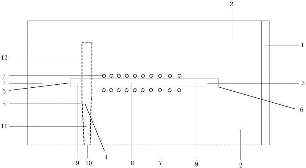
[0016] The embodiment adopted in the present invention is: the slot antenna of metal via step impedance comprises a dielectric substrate 1, a metal ground 2 arranged on the dielectric substrate 1, a radiation slot 3, and a microstrip feeder 4; one side of the dielectric substrate 1 is a metal Ground 2, the other side of the dielectric substrate 1 is the conduction band 5 of the microstrip feeder 4; there is a radiation slot 3 on the metal ground 2, the shape of the radiation slot 3 is a rectangle, and the radiation slot 3 is located at the center of the metal ground 2; The two ends 6 of the slot 3 are short-circuited; in the middle part of the radiation slot 3, there are two rows of metallized via hole 7 arrays on the two edges of the slot, so that the characteristic impedance of the middle part of the radiation slot 3 becomes low, forming a low The resistance slot 8; t...


PUM


Abstract

A slot antenna of metal via hole stepped-impedance relates to a slot antenna, and comprises a dielectric substrate (1), a metal ground (2) and a radiation slot (3) which are arranged on the dielectric substrate (1), and a micro-strip feeder line (4). The radiation slot (3) is arranged on the metal ground (2), and the two ends of the radiation slot (3) are in short circuit. Two rows of metallization via holes (7) at the middle part of the radiation slot (3) are in array arrangement to form a low-resistance slot (8), and the rest part of the radiation slot (3) is a high-resistance slot (9). One end of the micro-strip feeder line (4) is an antenna port (10), and the other end is in open circuit, spans the high-resistance slot (9) and extends a certain length. The antenna is in multi-frequency band work, enables the size and the shelter to be reduced and the isolation to be improved, and restrains the cross polarization.

Description

technical field [0001] The invention relates to a slot antenna, in particular to a slot antenna with metal via hole step impedance. Background technique [0002] The slot antenna is the dual antenna of the dipole antenna and has a wide range of applications. However, the ordinary slot antenna not only needs half the wavelength of the radiation slot itself, but also needs a large metal ground area around the radiation slot, usually the length of the metal ground is 1 / 2 larger than the length of the slot One wavelength, the width of the metal ground is one-half wavelength larger than the width of the slot. A larger metal ground will make the slot antenna unsuitable for multiple-input multiple-output (MIMO) applications, resulting in poor cross-polarization of the antenna, which will lead to a decrease in spectral efficiency and channel capacity. At the same time, the impedance of the slot is very large, which also makes it difficult to match the impedance of the slot antenna...

Claims


Application Information

Patent Timeline
IPC IPC(8): H01Q1/38H01Q1/48H01Q1/50H01Q5/10H01Q5/307H01Q13/10
CPCH01Q1/38H01Q1/48H01Q1/50H01Q5/10H01Q5/307H01Q13/10
Inventor 殷晓星齐宏业赵洪新
Owner SOUTHEAST UNIV
Why Eureka
Try Eureka