


Quick Research
Generate reliable direction feasibility study reports for your R&D in just a few steps.

Technical Q&A
Discover and master advanced knowledge NOW. Basics, ideas, possibilities, all at once.

Find Solutions
As an expert in R&D theories, this can generate solutions to your technical problems instantly.

Evaluate Feasibility
Analyze your overall solution with one click, know your potential R&D risks in advance.

Monitor Landscape
Get weekly tech updates, stay abreast of the latest tech innovations and key insights.
First-order sea clutter detection method based on least squares approximation
A least squares and detection method technology, applied in the field of high-frequency ground wave radar detection, can solve the problems of inaccurate Bragg peak position and high false alarm rate, reduce interference such as spectrum splitting and high-frequency noise, improve accuracy, Solve the effect of inaccurate recognition
- Summary
- Abstract
- Description
- Claims
- Application Information
AI Technical Summary
Problems solved by technology
Method used
Image

Examples
specific Embodiment approach 1
[0025] Specific implementation mode one: as Figure 8 As shown, the first-order sea clutter detection method based on the least squares approximation includes the following steps:
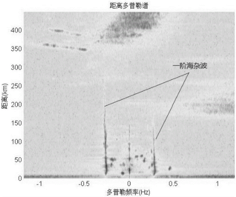
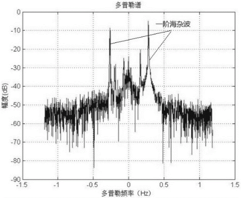
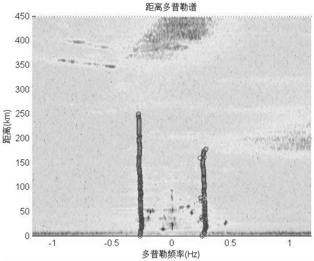
[0026] The original radar echo data undergoes two FFT operations and one DBF operation to obtain the azimuth-range-Doppler spectrum (ARD spectrum) of the echo data. The identification of the first-order sea clutter is to identify the position of the first-order Bragg peak on the ARD spectrum.
[0027] Step 1: From the operating frequency f of the radar 0 , get the theoretical Bragg frequency f B ;
[0028] Step 2: According to f obtained in step 1 B Delineate the noise area on each sea element, and obtain the threshold value of each sea element;
[0029] Step 3: According to the sea state data in the sea area detected by the radar, determine the maximum value V of the radial flow velocity of the ocean current m , and find the maximum value of the Bragg frequency offset Δf m ;
[0030] Step ...
specific Embodiment approach 2
[0048] Specific embodiment two: the difference between this embodiment and specific embodiment one is: obtain theoretical Bragg frequency f in the described step one B The formula is:
[0049] f B = ± 0.102 f 0 - - - ( 6 ) .
specific Embodiment approach 3
[0050] Specific implementation mode three: the difference between this implementation mode and specific implementation mode one or two is that: the threshold value obtained for each sea element in the step two is specifically:
[0051] The threshold for each sea element is N p and the sum of SNR, the N p is the base noise, and SNR (given according to the actual situation) is the set minimum signal-to-noise ratio.
[0052] In this algorithm, the Doppler frequency is in [-2f B ,2f B ] area is divided into noise area (the range of noise area can be adjusted according to the actual situation).
PUM
 Abstract
Description
Claims
Application Information
 - R&D Engineer
- R&D Manager
- IP Professional
- Industry Leading Data Capabilities
- Powerful AI technology
- Patent DNA Extraction
Browse by: Latest US Patents, China's latest patents, Technical Efficacy Thesaurus, Application Domain, Technology Topic, Popular Technical Reports.
© 2024 PatSnap. All rights reserved.Legal|Privacy policy|Modern Slavery Act Transparency Statement|Sitemap|About US| Contact US: help@patsnap.com