
Differential filtering microstrip array antenna having high common-mode rejection

A technology with high common-mode rejection and differential filtering, which is applied to antennas, antenna arrays, antenna grounding devices, etc., can solve problems such as hard-to-see filter microstrip array antennas, and achieve excellent common-mode rejection characteristics, good filtering characteristics, and excellent filtering Effect

Active Publication Date: 2016-08-17
SOUTH CHINA UNIV OF TECH
View PDF5 Cites 25 Cited by
  • Summary
  • Abstract
  • Description
  • Claims
  • Application Information

AI Technical Summary

Problems solved by technology

[0009] In general, it is difficult to see a filter microstrip array antenna working on a differential input in published articles and patents

Method used


Image

  • Differential filtering microstrip array antenna having high common-mode rejection
  • Differential filtering microstrip array antenna having high common-mode rejection
  • Differential filtering microstrip array antenna having high common-mode rejection

Examples


Embodiment Construction

[0028] The present invention will be further described below in conjunction with specific examples.

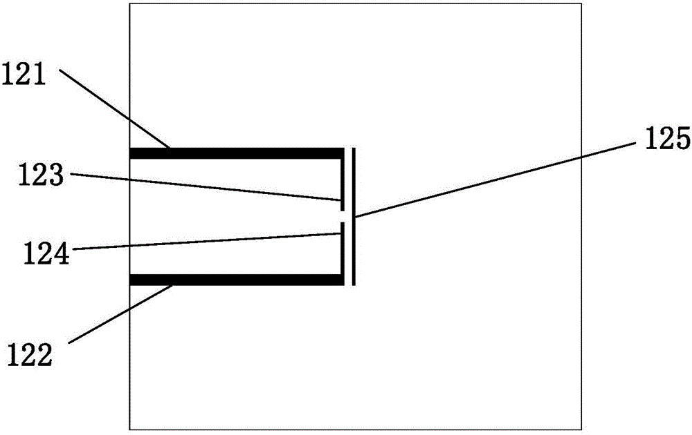
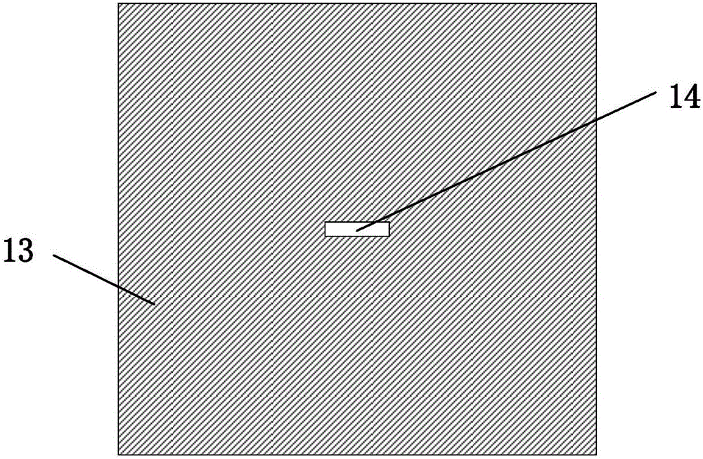
[0029] The differential filtering microstrip array antenna of the present invention is integrally fabricated on a multi-layer copper-clad dielectric substrate, and can be easily produced by techniques such as mechanical engraving, laser engraving, and circuit board corrosion. The core content of the present invention is that the antenna adopts a multi-layer structure structure, and the first two-order resonators are respectively placed on the first layer and the third layer, which are coupled through the gap of the second layer to achieve a natural high common-mode suppression effect, which is This kind of gap coupling can also make the two ends of the second-order resonator form a natural 180-degree phase difference, so that the second-order resonator has the function of a balun. At the same time, the second-order resonator is designed as an H shape, which can also realize a ...


PUM


Abstract

The invention discloses a differential filtering microstrip array antenna having high common-mode rejection. The antenna mainly comprises three layers of structures as follows: a feed network, a ground comprising a slot structure as well as four patch radiation units containing H-shaped resonator stimulation. The core content of the antenna is as follows: the antenna adopts the multiple layers of structures, first two orders of resonators are arranged at the first layer and the second layer respectively and are coupled through a slot at the second layer, the natural high common-mode rejection effect can be realized, and the natural 180-degree difference can also be formed at two ends of a second-order resonator by the aid of slot coupling, so that the second-order resonator has the Balun function; meanwhile, the second-order resonator is designed into the H shape and can further realize a power quartering function. Under the condition that no additional cascade filters exist and the area is increased, the antenna has the good filter characteristic and is minimized. In general, the antenna has the characteristics of high selectivity, high common-mode rejection, high gain, small size and the like.

Description

technical field [0001] The invention relates to the technical field of wireless communication, in particular to a differential filter microstrip array antenna with high common-mode rejection. Background technique [0002] In recent years, communication systems are developing towards miniaturization and multi-function. Antennas and RF / microwave filters, as key components in communication, are usually designed independently and then connected through transmission lines, but in many cases, if the operating bandwidths of antennas and filters are different, their input impedances often cannot be completely matched, which will affect the frequency characteristics . If a separate matching circuit design is performed, the design will be complicated and the size of the device will be increased. The integrated filter antenna realizes the dual functions of filtering and radiation, which is conducive to the miniaturization of the RF front-end, and can reduce the volume and cost of com...

Claims


Application Information

Patent Timeline
IPC IPC(8): H01Q1/38H01Q1/48H01Q1/50H01Q21/00
CPCH01Q1/38H01Q1/48H01Q1/50H01Q21/0075
Inventor 陈付昌胡豪涛
Owner SOUTH CHINA UNIV OF TECH
Learn More