
Reconfigurable substrate integrated waveguide bandpass filter and reconfigurable method of filter

A substrate-integrated waveguide and band-pass filter technology, which is applied to waveguide-type devices, electrical components, circuits, etc., can solve the problems that the control voltage of the varactor diode cannot be directly applied, the filter insertion loss is large, and the control structure is complicated. To achieve the effect of simple and flexible design, size reduction, and reconfiguration

Active Publication Date: 2016-08-17
XIDIAN UNIV +1
View PDF3 Cites 17 Cited by
  • Summary
  • Abstract
  • Description
  • Claims
  • Application Information

AI Technical Summary

Problems solved by technology

[0006] At present, there are relatively few reconfigurable substrate-integrated waveguide bandpass filters based on varactor diodes. The reason is that the metal pillars on one side of the substrate-integrated waveguide directly connect the ground plate and the upper surface of the substrate-integrated waveguide. The control voltage of the diode cannot be directly added to the substrate integrated waveguide
The existing method is to connect the varactor diode between the resonant ring and the metal floating capacitor, and realize the adjustment and control of the resonant ring capacitance through the capacitive effect of the metal floating capacitor. The control structure is complex and the filter insertion loss is large, and the adjustable range is small.

Method used


Image

  • Reconfigurable substrate integrated waveguide bandpass filter and reconfigurable method of filter
  • Reconfigurable substrate integrated waveguide bandpass filter and reconfigurable method of filter
  • Reconfigurable substrate integrated waveguide bandpass filter and reconfigurable method of filter

Examples


Embodiment 1

[0035] At present, most of the band-pass filters based on the substrate-integrated waveguide form are etched resonant rings of different shapes on the surface of the substrate. Although the structure is simple, it is not suitable for multi-band applications. In order to apply to multi-band applications, it is necessary to design multiple filters with different frequency bands. The engineering is more complicated, which not only causes waste of design and resources, but also inconveniences in use and time delay. Now it is necessary to process multi-band signals. For RF front-end circuits, there is an urgent need for a reconfigurable substrate-integrated waveguide bandpass filter.

[0036]The varactor is a low-cost and easy-to-control tunable device. At present, most of the microwave tunable filters based on the varactor are implemented on the microstrip. The substrate-integrated waveguide bandpass filter is still relatively few, because the metal column on one side of the subst...

Embodiment 2

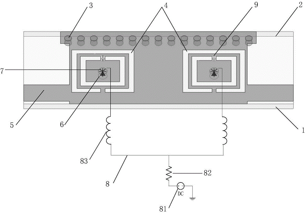
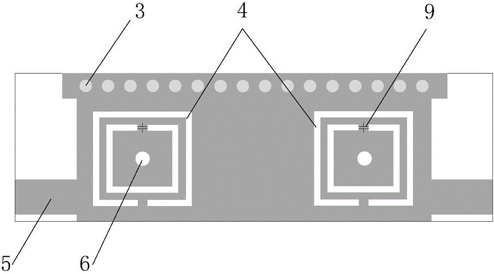
[0041] The overall composition and structural characteristics of the reconfigurable substrate-integrated waveguide bandpass filter are the same as those in Example 1. The non-metallized via hole is arranged in the center of the resonant ring, and the diameter of the via hole is the same as the structure size of the varactor placed in the via hole. Matching, the margin between the diameter of the via hole and the structure size of the varactor diode is 0.1mm, which ensures that the varactor diode is easy to weld with the metal layer of the integrated waveguide on the substrate, and ensures the stability of the varactor diode in the via hole; The diameter of the metallized via should not be too large, otherwise it will affect the continuity of the field in the integrated waveguide of the substrate, and the filtering performance will be deteriorated. In this example, the model of the varactor diode is SMV1405.

Embodiment 3

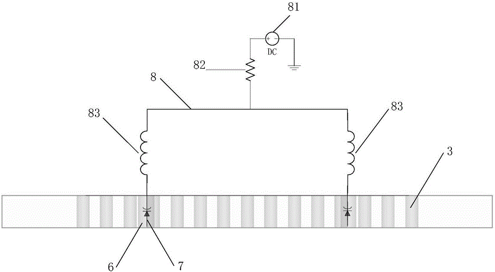
[0043] The overall composition and structural features of the reconfigurable substrate-integrated waveguide bandpass filter are the same as those in Embodiment 1-2, see figure 1 and image 3 In the present invention, a DC blocking capacitor 9 is installed at the opening of the inner ring of the resonance ring. One end of the DC blocking capacitor is connected to the metal sheet between the inner and outer rings of the resonance ring, and the other end is connected to the metal sheet inside the resonance ring. The width of the inner and outer rings of the two resonant rings is the same, and the width matches the structure size of the DC blocking capacitor, so that the DC blocking capacitor can just be connected to the inner ring, ensuring the safety and reliability of the reconfigurable substrate integrated waveguide bandpass filter Work. The placement of the DC blocking capacitor 9 enables the DC voltage to be applied to both ends of the varactor diode, without causing a shor...


PUM

PropertyMeasurementUnit
Thicknessaaaaaaaaaa
Return lossaaaaaaaaaa

Abstract

The invention discloses a reconfigurable substrate integrated waveguide bandpass filter and a reconfigurable method of the filter and mainly solves technical problems that the tuning range is small, the insertion loss of reconfigurable substrate integrated waveguide bandpass filters is high and control voltage of variable capacitance diodes cannot be directly applied to substrate integrated waveguides. One variable capacitance diode is placed in a non-metal via hole formed in the center of each of two complementary split-ring resonators of the bandpass filter, the metal part at an inner ring opening of each complementary split-ring resonator is replaced with a blocking capacitor, so that a substrate integrated waveguide is separated from an outer circuit, and a voltage source is prevented from being short-circuited; the variable capacitance diodes are connected with a direct-current bias circuit, reversed bias voltage at two ends of the variable capacitance diodes is adjusted, junction capacity of the variable capacitance diodes is changed, so that the resonant frequency of the two complementary split-ring resonators is affected, and the passband center frequency is reconfigurable. The feeding manner of the variable capacitance diodes in the substrate integrated waveguide is realized, the control manner is simple and easy to implement, the frequency tuning range is relatively large, the in-band insertion loss is low, and the filter can be applied to a wireless communication system.

Description

technical field [0001] The invention belongs to the technical field of electronic devices, in particular to a substrate-integrated waveguide bandpass filter, in particular to a reconfigurable substrate-integrated waveguide bandpass filter and a reconfigurable method thereof, which are used for the radio frequency front end of a wireless communication system. Background technique [0002] With the development and innovation of modern wireless communication systems, microwave and millimeter-wave systems are rapidly developing towards miniaturization, high integration, and low cost. The waveguide structure with low loss, high quality factor and high power capacity has been widely used due to its excellent performance, but its size and volume are too large to be suitable for applications with high miniaturization and high integration; while traditional microstrip Although the structure has large radiation, due to its small size and simple processing, it can meet the volume and i...

Claims


Application Information

Patent Timeline
IPC IPC(8): H01P1/203
CPCH01P1/203
Inventor 魏峰宋井盼康宏毅黄丘林史小卫
Owner XIDIAN UNIV
Learn More