
Top plate ejecting system for ejecting closure section of continuous rigid frame bridge and construction method thereof

A technology for rigid frame bridges and closing sections, which is applied in bridges, bridge construction, erection/assembly of bridges, etc. It can solve problems such as large bending moments, low connection strength between the base and the roof, and few ordinary U-shaped connection steel bars.

Inactive Publication Date: 2016-08-17
XIAN HIGHWAY INST
View PDF5 Cites 3 Cited by
  • Summary
  • Abstract
  • Description
  • Claims
  • Application Information

AI Technical Summary

Problems solved by technology

[0010] However, the existing roof pre-embedded base mostly adopts the technical scheme of welding U-shaped connecting steel bars under the steel plate and embedding the steel bars in the roof concrete. Less, the connection strength between the base and the roof is low; second, the U-shaped connecting steel bars and the original steel bars of the box girder roof cannot be fully combined; The surface connection forms a local weak zone; fourth, the workload of component welding is heavy
In addition, the existing pre-embedded base of the roof also has a technical solution that adopts the vertical insertion of section steel into the concrete as the push-up reaction point. This solution has the following defects: first, the position of the push-up point is relatively high, and the local concrete of the pre-buried base is affected. In addition to the shear force in the jacking direction, there is still a large bending moment that needs to be borne by the section steel and surrounding concrete, which is not conducive to giving full play to the compressive characteristics of the concrete; second, after the completion of the jacking construction, it is necessary to cut off part of the section steel that protrudes
[0011] Nowadays, when pushing the closing section of a continuous rigid frame bridge, usually no special reaction frame is set up, but the embedded steel bracket is used as the base to take into account the reaction frame, and there are also rigid struts directly connected to the embedded base ( That is, the method of the outer rigid support structure), cutting off the part that affects the concrete of the bridge deck pavement after the jacking is completed, but the above-mentioned existing construction schemes all have the following defects: first, the locking and pushing positions are located in the outer rigid support structure The middle part of the outer rigid support structure is complex due to the need to set a jack, and the overall rigidity of the outer rigid support structure is reduced; second, the locking is performed by on-site welding, which is troublesome in construction, and the error is not easy to adjust after welding and locking; third, After the jacking and concrete pouring are completed, it needs to be cut and dismantled, and the reuse rate is low; Fourth, the center of gravity of the component is high, and the additional bending moment is large during the jacking
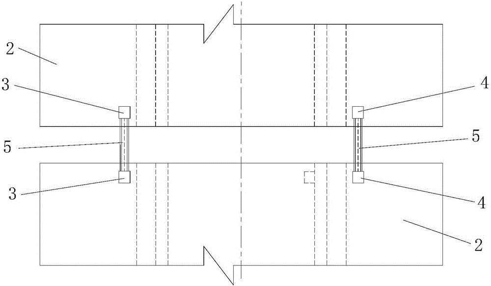
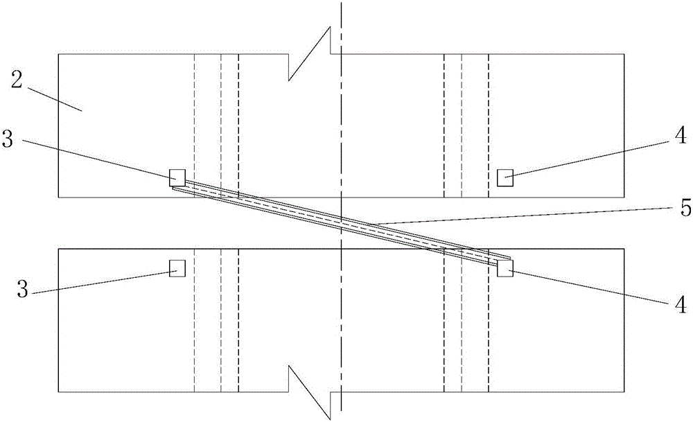
But at present, there is a lack of a counter force frame capable of oblique thrusting, and it is impossible to perform oblique thrusting

Method used


Image

  • Top plate ejecting system for ejecting closure section of continuous rigid frame bridge and construction method thereof
  • Top plate ejecting system for ejecting closure section of continuous rigid frame bridge and construction method thereof
  • Top plate ejecting system for ejecting closure section of continuous rigid frame bridge and construction method thereof

Examples


Embodiment 2

[0264] Such as Figure 8 As shown, in this embodiment, the difference from Embodiment 1 is that the rigid support is a second support, and the second support is composed of two symmetrically arranged support angle steels 5-2-2, and the two The supporting angle steel 5-2-2 is welded and fixed on the lower supporting steel plate 8-1.

[0265]In this embodiment, the rest of the structure and connections of the roof pushing system used are the same as those in Embodiment 1.

[0266] In this embodiment, the construction method of the roof pushing system adopted is the same as that in Embodiment 1.

Embodiment 3

[0268] Such as Figure 9 As shown, in this embodiment, the difference from Embodiment 1 is that the rigid support is a third support, and the third support is supported by two symmetrically arranged vertical steel plates 5-2-3 on the left and right It consists of an upper supporting steel plate 5-2-4 on the two vertical steel plates 5-2-3. Moreover, the two vertical steel plates 5-2-3 are welded and fixed on the lower supporting steel plate 5-1. The upper supporting steel plate 5-2-4 is a rectangular steel plate and its size is the same as that of the lower supporting steel plate 5-1, and the upper supporting steel plate 5-2-4 and the two vertical steel plates 5-2-3 All are fixedly connected by welding.

[0269] In this embodiment, the rest of the structure and connections of the roof pushing system used are the same as those in Embodiment 1.

[0270] In this embodiment, the construction method of the roof pushing system adopted is the same as that in Embodiment 1.


PUM


Abstract

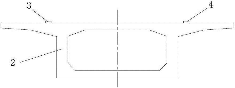
The invention discloses a top plate ejecting system for ejecting closure section of a continuous rigid frame bridge and a construction method thereof. The top plate ejecting system comprises two groups of top plate pre-buried bases, a rigid support structure and an ejecting mechanism, wherein the two groups of top plate pre-buried bases are respectively arranged at two cantilever beam section ends of the continuous rigid frame bridge; the rigid support structure is supported between the two groups of top plate pre-buried bases; the ejecting mechanism is used for ejecting the rigid support structure; each group of top plate pre-buried bases comprises a left top plate pre-buried base and a right top plate pre-buried base arranged on the same cantilever beam sections; the rigid support structure is a longitudinal ejecting support structure or an oblique ejecting support structure; one end of the rigid support structure is a fixed end, and the other end of the rigid support structure is an ejecting end. The construction method comprises the following steps: step one, constructing the top plate pre-buried bases; step two, mounting the ejecting mechanism; and step three, mounting the rigid support structure. The top plate ejecting system is reasonable in design, simple and convenient to construct and good in using effect; the process of ejecting the cantilever beam sections of the closure section can be simply, conveniently and quickly completed; and the requirements on correction of lateral deviation and torsion deviation of the cantilever beam sections can be met.

Description

technical field [0001] The invention belongs to the technical field of bridge construction, and in particular relates to a roof pushing system and a construction method thereof for pushing the closing section of a continuous rigid frame bridge. Background technique [0002] The continuous rigid frame bridge is a continuous girder bridge with piers and girders consolidated. The multi-span rigid frame bridge and the multi-span continuous-rigid frame bridge whose main span is divided into continuous girders all adopt prestressed concrete structure. There are more than two main piers. The pier-beam consolidation system has the advantages of T-shaped rigid frame bridges and continuous girder bridges. Closing section is the key link in the construction of continuous rigid frame bridge. In order to reduce the adverse effects of concrete shrinkage and creep and temperature changes on the bridge structure during the operation period, during the construction of the closing section of ...

Claims


Application Information

Patent Timeline
IPC IPC(8): E01D21/06E01D21/10
CPCE01D21/06E01D21/10
Inventor 袁卓亚蒲广宁王卫山龚晓晖王旭杜进生徐希娟宋彬张亚军张名成
Owner XIAN HIGHWAY INST
Learn More