Outer rotational flow limited flow channel membrane separator and method for demulsifying emulsion membrane through same

A technology of membrane separator and external swirling flow, which is applied in separation methods, semi-permeable membrane separation, chemical instruments and methods, etc. It can solve the problems of reduced separation efficiency, aggravated plugging, and short installation time, and achieves good demulsification effect , good permeability, good self-cleaning effect

Inactive Publication Date: 2016-08-10
CHANGCHUN UNIV OF TECH
View PDF4 Cites 7 Cited by
  • Summary
  • Abstract
  • Description
  • Claims
  • Application Information

AI Technical Summary

Problems solved by technology

The reason is that when the emulsion passes through the external swirl membrane separator, the emulsion runs in a spiral motion track at the beginning, and as the internal water phase separates, the resistance of the emulsion to do the spiral motion increases, and due to the gravity factor of the emulsion itself, the emulsion The trajectory of the movement in the separator changes dramatically, the flow rate of the emulsion decreases, and the chance of collision and friction between the emulsions and be...

Method used


Image

  • Outer rotational flow limited flow channel membrane separator and method for demulsifying emulsion membrane through same
  • Outer rotational flow limited flow channel membrane separator and method for demulsifying emulsion membrane through same
  • Outer rotational flow limited flow channel membrane separator and method for demulsifying emulsion membrane through same

Examples


Embodiment Construction

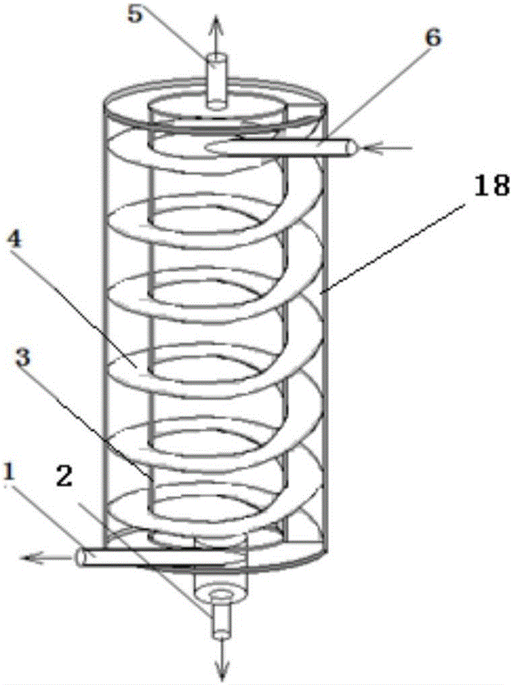
[0019] An external swirling flow restrictor membrane separator and its method for demulsifying emulsion liquid membrane, such as figure 1 with figure 2 As shown, the external swirl flow restrictor membrane separator includes a round tube housing 18, an emulsion outlet 1, an inner water phase material liquid outlet 2, a membrane separation tube 3, a restrictor swirl plate 4, a pressure measuring port 5, and a material Inlet 6, the round tube shell 18 is a cylindrical hollow tube; the emulsion outlet 1 is horizontally arranged at the lower part of the round tube shell 18; the inner water phase material liquid outlet 2 is arranged at the bottom center of the round tube shell 18; The membrane separation tube 3 is arranged inside the circular tube shell 18 and is arranged concentrically with the cross-sectional circle of the circular tube shell 18; the restrictor swirl plate 4 is spirally shaped along the outside of the membrane separation tube 3 It is arranged on the outside of the...


PUM


Abstract

The invention discloses an outer rotational flow limited flow channel membrane separator and a method for demulsifying an emulsion membrane through the same, and belongs to the technical field of chemical technology and chemical equipment .The outer rotational flow limited flow channel membrane separator comprises a round pipe shell, an emulsion outlet, an internal water phase material liquid outlet, a membrane separation pipe, a limited flow channel rotational flow plate, a pressure measuring opening and a material inlet .A round pipe is a cylindrical hollow pipe .The emulsion outlet is horizontally arranged on the lower portion of the round pipe .The internal water phase material liquid outlet is arranged in the center of the bottom of the round pipe .The membrane separation pipe is arranged inside the round pipe and is concentric with the cross section circle of the round pipe .The limited flow channel rotational flow plate is spirally arranged on the outer side of the membrane separation pipe and the inner side of the round pipe along the outer side of the membrane separation pipe .The material inlet is horizontally arranged on the upper portion of the round pipe and is parallel to the emulsion outlet .Emulsion can be forced to do constant screw-pitch rotational motion, namely approximately constant-speed rotational motion between spiral plates, the emulsion runs in the state of initially entering the membrane separator, the running time is long, the demulsifying rate is high, and the outer rotational flow limited flow channel membrane separator can be developed to be applied in demulsifying practical production .

Description

Technical field [0001] The invention belongs to the technical field of chemical processes and chemical equipment, and particularly relates to a method for demulsifying an emulsion liquid film of an external swirl flow restrictor membrane separator. Background technique [0002] Emulsion liquid membrane separation technology is an effective method to recover heavy metal ions from wastewater, but emulsion liquid membrane demulsification is the key to extracting and recovering heavy metal ions from the internal water phase and reusing the emulsion. Emulsion demulsification methods include standing method, distillation method, plasma method, electric demulsification method, microwave radiation method, ultrasonic demulsification method, centrifugal demulsification method, electrolyte method, chemical demulsifier demulsification method, and biological demulsification method , Grinding demulsification method, membrane separation method, etc. The process and equipment of the standing me...

Claims


Application Information

Patent Timeline
IPC IPC(8): B01D17/04B01D65/02B01D63/06
CPCB01D17/047B01D63/06B01D65/02
Inventor 石秀敏温春阳单绍雷杨永恒王树江张国馗
Owner CHANGCHUN UNIV OF TECH
Why Eureka
Try Eureka