
Fuel metering unit for a high-pressure injection system

A technology of fuel dosing and components, applied in the direction of low-pressure fuel injection, low-pressure fuel injection, charging system, etc., which can solve the problems of troublesome and expensive manufacturing of fuel dosing units

Inactive Publication Date: 2016-07-27
ROBERT BOSCH GMBH
View PDF8 Cites 5 Cited by
  • Summary
  • Abstract
  • Description
  • Claims
  • Application Information

AI Technical Summary

Problems solved by technology

Due to the seal and the required two separate bearing arrangements, the fuel metering unit is complex and expensive to manufacture

Method used


Image

  • Fuel metering unit for a high-pressure injection system
  • Fuel metering unit for a high-pressure injection system
  • Fuel metering unit for a high-pressure injection system

Examples


Embodiment Construction

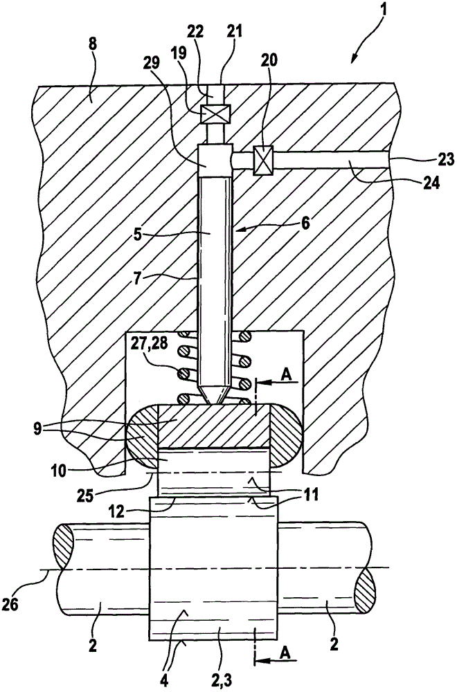
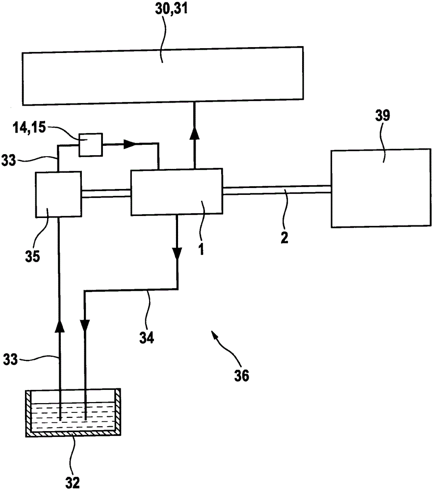
[0033] exist figure 1 shows a cross-section through a high-pressure pump 1 for delivering fuel. The high-pressure pump 1 serves to deliver fuel, such as diesel or gasoline, to the internal combustion engine 39 at high pressure. The pressure that can be generated by the high-pressure pump 1 is, for example, in the range between 1000 and 3000 bar.

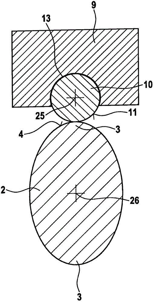
[0034] The high-pressure pump 1 has a drive shaft 2 with two cams 3 , which executes a rotational movement about an axis of rotation 26 . The axis of rotation 26 is located at figure 1 in the plane of the graph and perpendicular to figure 2figure plane. The piston 5 is mounted in a cylinder 6 which is formed by a housing 8 . A working chamber 29 is delimited by the cylinder 6 , the housing 8 and the piston 5 . An inlet channel 22 with inlet valve 19 and an outlet channel 24 with outlet valve 20 open into a working chamber 29 . The fuel flows through the inlet channel 22 into the working chamber 29 and the fuel under high pres...


PUM


Abstract

The invention relates to a valve (14), in particular a fuel-metering unit (15), comprising a valve cylinder (16), a valve piston (17) which is movable within the valve cylinder (16) between a closed position and open position such that in the closed position the valve (14) is closed and in the open position the valve (14) is open, a resilient valve element (37), in particular a valve spring (38), which is connected to the valve piston (17) and by means of which valve spring a force can be applied to the valve piston (17) in the opposite direction to a force which can be applied by an electromagnet (40) to the valve piston (17), such that the valve piston (17) can be moved between the closed position and the open position by means of the force applied by the resilient valve element (37) and the electromagnet (40) to the valve piston (17), the electromagnet (40) with a coil (41) for moving the valve piston (17), a movable armature (42), which is mechanically operatively connected to the valve piston (17), for moving the valve piston (17), a plastic housing (18) which is constructed radially outside the coil (41), wherein the plastic housing (18) is additionally constructed radially inside the coil (41).

Description

technical field [0001] The invention relates to a valve according to the preamble of claim 1 and a high-pressure injection system according to the preamble of claim 14 . Background technique [0002] In high-pressure injection systems for internal combustion engines, in particular common-rail injection systems for diesel or gasoline engines, a high-pressure pump is continuously used to maintain the pressure in the high-pressure accumulator of the common-rail injection system. The high-pressure pump can be driven, for example, by means of a camshaft of the internal combustion engine via a drive shaft. To feed fuel to the high-pressure pump, a pre-feed pump, such as a gear pump or a rotary slide valve pump, is used, which is connected upstream of the high-pressure pump. The pre-feed pump delivers fuel from the fuel tank through the fuel line to the high-pressure pump. [0003] Piston pumps are also used as high-pressure pumps. A drive shaft is supported in the housing. In ...

Claims


Application Information

Patent Timeline
Patent Type & Authority Applications(China)
IPC IPC(8): F02M59/36F02M69/18
CPCF02M59/366F02M69/18F02M2200/8046F02M2200/9015
Inventor A·梅西克S·科尔布T·兰登贝格尔H·黑贝尔
Owner ROBERT BOSCH GMBH
Learn More