LED light emitting device and backlight module using the LED light emitting device

A light-emitting device and LED chip technology, which is applied in semiconductor devices, electric solid-state devices, electrical components, etc., can solve problems such as large amount of powder consumption, poor moisture and oxygen resistance of quantum dots, and slow development of new green phosphor powder, etc., to achieve High reliability, improved excitation efficiency, and rich color expression effects

Active Publication Date: 2019-01-25
APT ELECTRONICS
View PDF4 Cites 0 Cited by
  • Summary
  • Abstract
  • Description
  • Claims
  • Application Information

AI Technical Summary

Problems solved by technology

[0003] However, most quantum dots (QDs) contain heavy metal cadmium (Cd), which is strictly prohibited in the EU, and quantum dots (QDs) themselves have poor moisture and oxygen resistance.
For traditional LED red / green phosphors, its NTSC color gamut is 20% lower than that of quantum dots (QD), which is difficult to meet the needs of the high-end market
In recent years, the NTSC color gamut obtained by using narrow half-wave width red phosphors combined with traditional LED green phosphors has been greatly improved, but it is still about 10% lower than that of quantum dots (QDs), that is, it is difficult to get close to QDs. Achieved NTSC color gamut
[0004] In addition, a new type of green phosphor with a narrow half-wave width (usually below 40nm) excited by violet light is used in LED packaging, and its NTSC color gamut is close to that of QD, but the narrow half-wave The development of wide new green phosphors is progressing slowly, and the blue light excitation efficiency is low, resulting in a large amount of powder used, making the proportion of phosphors exceed that of silica gel, resulting in the inability to achieve mass production

Method used


Image

  • LED light emitting device and backlight module using the LED light emitting device

Examples


Embodiment 1

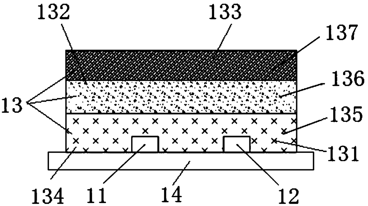
[0039] This embodiment provides an LED light emitting device, such as figure 1 Shown:

[0040] Including the purple LED chip 11, the blue LED chip 12 and the fluorescent glue 13, both the purple LED chip 11 and the blue LED chip 12 are installed on the packaging substrate 14, and the light emitting surfaces of the purple LED chip 11 and the blue LED chip 12 are all facing upward , wherein the dominant wavelength of the blue LED chip 12 is 452.5nm, and the dominant wavelength of the purple LED chip 11 is 400nm.

[0041] Specifically, the fluorescent glue 13 includes a first fluorescent layer 135 , a second fluorescent layer 136 and a third fluorescent layer 137 . The first fluorescent layer 135 is formed by uniformly mixing nitrogen oxide green fluorescent powder 131 and silica gel 134. The specific process method is: respectively weigh corresponding weights of nitrogen oxide green fluorescent powder 131 and silica gel 134, mix them uniformly, and remove It can be made by soa...

Embodiment 2

[0047] This embodiment provides another LED light emitting device, which differs from the LED light emitting device described in Embodiment 1 in that:

[0048] (1) The dominant wavelength of the violet LED chip 11 is 410nm;

[0049] (2) The weight of the nitrogen oxide green phosphor powder 131 is equal to that of the nitrogen oxide green phosphor powder 131, the green phosphor powder 132 with a half-wave width below 40nm and Mn 4+ The mass percentage in the total weight of the activated fluoride red phosphor powder 133 is 2%;

[0050] (3) The peak wavelength of the green phosphor 132 mainly excited by purple light with a half-wave width below 40nm is 517nm;

[0051] (4) The NTSC color gamut of the LED light emitting device provided in this embodiment can be increased by 10%.

[0052] The rest of the technical solutions and other technical effects of this embodiment are completely the same as those of Embodiment 1, and will not be repeated here.

[0053] This embodiment als...

Embodiment 3

[0055] This embodiment provides another LED light emitting device, which differs from the LED light emitting device described in Embodiment 1 in that:

[0056] (1) The weight of nitrogen oxide green phosphor powder 131 is equal to that of nitrogen oxide green phosphor powder 131, green phosphor powder 132 with a half-wave width below 40nm and Mn 4+ The mass percentage of the total weight of the activated fluoride red phosphor powder 133 is 8%;

[0057] (2) SrMgAlO / EuMn (strontium magnesium aluminate) is specifically selected as the green phosphor 132 mainly excited by purple light with a half-wave width below 40nm, and its peak wavelength is 515nm;

[0058] (3) The NTSC color gamut of the LED light-emitting device provided by this embodiment can be increased by 6%; compared with Embodiment 1, the brightness of the lamp bead packaging of the LED light-emitting device provided by this embodiment can be improved by 2% to 3%, and the package is to For the same color point (0.26, ...


PUM


Abstract

The invention discloses a light emitting diode (LED) luminous device. The LED luminous device comprises a purple-light LED chip, a blue-light LED chip and a fluorescent adhesive, wherein the fluorescent adhesive covers the purple-light LED chip and the blue-light LED chip and comprises nitrogen oxide green fluorescent powder, green fluorescent powder with half-wave width below 40 nanometers, Mn<4+> activated fluoride red fluorescent powder and silica gel, and the mass percent of the weight of the nitrogen oxide green fluorescent powder in the total weight of the nitrogen oxide green fluorescent powder, the green fluorescent powder with half-wave width below 40 nanometers and the Mn<4+> activated fluoride red fluorescent powder is less than or equal to 25%. The invention also discloses a backlight module employing the LED luminous device. By the LED luminous device, high color gamut can be acquired, mass production also can be achieved, and the reliability is high. When the LED luminous is applied to the backlight module, a fabricated LED television is approximate to a quantum dot (QD) television in national television system committee (NTSC) gamut, and audience acquires favorable visual experience.

Description

technical field [0001] The invention belongs to the technical field of light-emitting diodes (LEDs), and in particular relates to an LED light-emitting device and a backlight module using the LED light-emitting device. Background technique [0002] The color performance can be quantitatively measured by the NTSC color gamut. The higher the NTSC color gamut, the richer the color. The NTSC color gamut of ordinary LED TVs is only 72%, while the NTSC color gamut coverage of quantum dot (QD) TVs is as high as 110%. Therefore, in recent years, under the trend of TVs with high color performance being popular, quantum dot TVs are widely sold. [0003] However, most quantum dots (QDs) contain heavy metal cadmium (Cd), which is strictly prohibited in the European Union, and quantum dots (QDs) themselves have poor moisture and oxygen resistance. For traditional LED red / green phosphors, its NTSC color gamut is 20% lower than that of quantum dots (QD), which is difficult to meet the ne...

Claims


Application Information

Patent Timeline
Patent Type & Authority Patents(China)
IPC IPC(8): H01L25/075H01L33/50
CPCH01L25/0753H01L33/504H01L33/505
Inventor 龙小凤姚述光姜志荣万垂铭曾照明肖国伟区伟能
Owner APT ELECTRONICS
Why Eureka
Try Eureka