a color image
A color image and color technology, applied in optical components, instruments, optics, etc., can solve problems such as limiting image effects, difficulty in preparing color images with pixel units smaller than 5 microns, and limiting image resolution, so as to improve resolution and enhance Display effect, color expression rich effect
- Summary
- Abstract
- Description
- Claims
- Application Information
AI Technical Summary
Problems solved by technology
Method used
Image

Examples
Embodiment 1
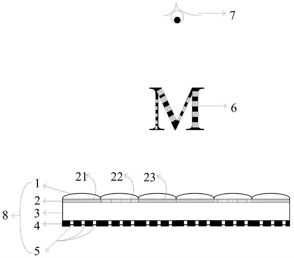
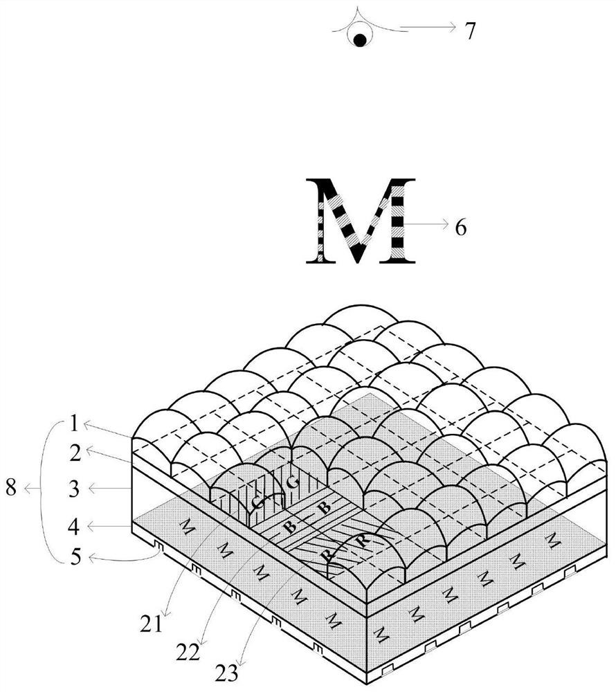
[0047] This embodiment provides a thin-film color image under scattered light illumination, as shown in the attached figure 1 to attach figure 2 As shown, the color image 8 includes a focusing element array layer 1 , a first dyed layer 2 , a substrate layer 3 , a micropattern array layer 4 and a second dyed layer 5 bonded in sequence. The focusing element array is formed by orthogonal arrangement of spherical microlens units with square apertures. The first dyed layer 2 is composed of transmissive red, green and blue three-color pigments arranged in an orthogonal array of pixel lattices. A pixel point of one color on the first dyed layer 2 corresponds to one spherical microlens unit. The micro-pattern array layer 4 is formed by arranging orthogonally arranged groove-type micro-pattern units on the lower surface of the substrate layer 3, and the pixel size of the micro-pattern units is 10 microns. The second dyed layer 5 is filled with white pigments in the grooves of the g...
Embodiment 2
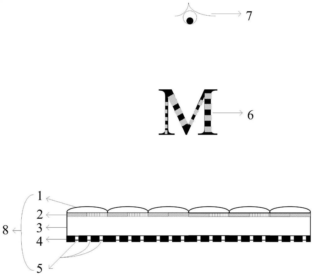
[0051] This embodiment provides a thin-film color image under scattered light illumination, as shown in the attached image 3 As shown, the color image 8 includes a focusing element array layer 1 , a first dyed layer 2 , a substrate layer 3 , a micropattern array layer 4 and a second dyed layer 5 bonded in sequence. The focusing element array is formed by a honeycomb arrangement of spherical microlens units with a hexagonal aperture.
[0052] Specifically, the first dyed layer 2 is formed by a honeycomb arrangement of color pixel lattices composed of transmissive red, green and blue pigments. The color pixels of two colors on the first dyed layer 2 correspond to one microlens unit to form richer colors. The micro-pattern array layer 4 is formed by setting honeycomb-arranged groove-type micro-pattern units on the lower surface of the substrate layer, and the pixel size of the micro-pattern units is 4 microns. The second dyed layer 5 is filled with white pigments in the groove...
Embodiment 3
[0055] This embodiment provides a thin-film color image under scattered light illumination, as shown in the attached Figure 4 As shown, the color image 8 includes a focusing element array layer 1 , a first dyed layer 2 , a substrate layer 3 , a micropattern array layer 4 and a second dyed layer 5 bonded in sequence.
[0056] Preferably, the array of focusing elements is formed by orthogonal arrangement of aspherical microlens units with circular apertures.
[0057] Preferably, the first dyed layer 2 is formed by an orthogonal arrangement of color pixel lattices composed of transmissive red, green and blue pigments. A color pixel point of one color on the first dyed layer 2 corresponds to one microlens unit. The color pixels corresponding to the different microlens units have different sizes, and the saturation of the corresponding color can be adjusted by adjusting the size of the color pixels.
[0058] Further, the micro-pattern array layer 4 is formed by arranging orthogo...
PUM
| Property | Measurement | Unit |
|---|---|---|
| size | aaaaa | aaaaa |
| size | aaaaa | aaaaa |
| size | aaaaa | aaaaa |
Abstract
Description
Claims
Application Information
 - R&D
- Intellectual Property
- Life Sciences
- Materials
- Tech Scout
- Unparalleled Data Quality
- Higher Quality Content
- 60% Fewer Hallucinations
Browse by: Latest US Patents, China's latest patents, Technical Efficacy Thesaurus, Application Domain, Technology Topic, Popular Technical Reports.
© 2025 PatSnap. All rights reserved.Legal|Privacy policy|Modern Slavery Act Transparency Statement|Sitemap|About US| Contact US: help@patsnap.com