
Total internal reflection microscopy method and device based on free-form surface shaping

A total internal reflection and free technology, applied in microscopes, optics, instruments, etc., can solve the problems of uneven light field and low utilization rate of light energy, and achieve uniform imaging field of view, high utilization rate of laser energy and low noise Effect

Inactive Publication Date: 2016-07-27
ZHEJIANG UNIV
View PDF6 Cites 16 Cited by
  • Summary
  • Abstract
  • Description
  • Claims
  • Application Information

AI Technical Summary

Problems solved by technology

However, due to the existence of laser speckle, the light field will be inhomogeneous
For this reason, the invention of a rotating total internal reflection microscope system (Ring-tirf) has evened the illumination light field by means of rotation, and there are two methods for realizing the rotation, such as the vibrating mirror proposed by the patent application number CN103597396A method and digital micromirror (DMD), but these two methods have their own defects. The galvanometer method cannot avoid angle vibration, and the method of digital micromirror will lead to a relatively low utilization rate of light energy, only about 5%.

Method used


Image

  • Total internal reflection microscopy method and device based on free-form surface shaping
  • Total internal reflection microscopy method and device based on free-form surface shaping
  • Total internal reflection microscopy method and device based on free-form surface shaping

Examples


Embodiment Construction

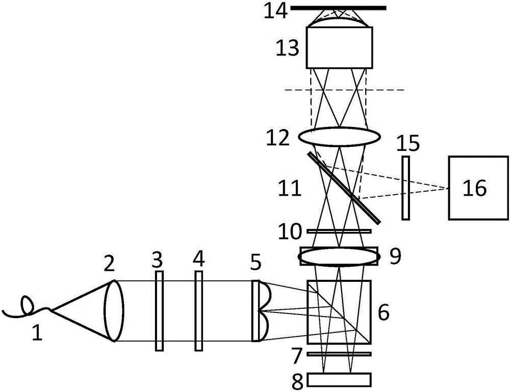
[0036] Such as figure 1 As shown, a total internal reflection microscopy device based on free-form surface shaping includes: fiber laser 1, collimator lens 2, polarizer 3, half-wave plate 4, free-form surface lens 5, polarization beam splitter prism (PBS )6, quarter-wave plate 7, digital micromirror (DMD) 8, variable focal length collimating lens 9, quarter-wave plate 10, dichromatic mirror 11, microscopic field lens 12, total internal reflection microscope Micro objective lens 13, sample 14, optical filter 15 and CCD16.

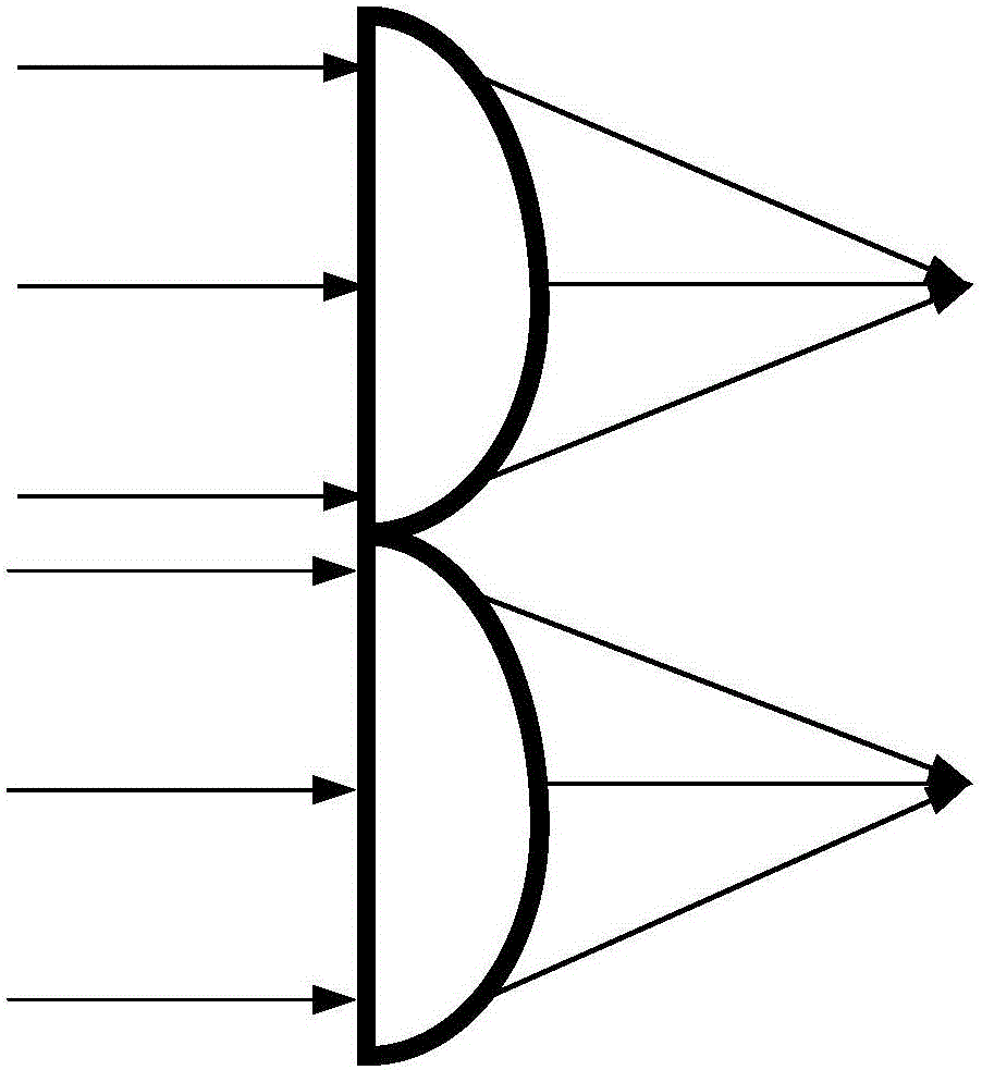
[0037]Laser 1, collimator lens 2, polarizer 3, half-wave plate 4 and free-form surface lens 5 are centered on the same optical axis, the laser light emitted by laser 1 becomes a parallel beam through collimator lens 2, and polarizer 3 makes The light beam becomes linearly polarized light, the half-wave plate 4 can change the polarization direction of the polarized light, and the free-form surface lens 5 can focus the light beam into an annular light spot, s...


PUM


Abstract

The invention discloses a total internal reflection microscopy device based on free-form surface shaping.The device comprises a light source and a line polarized light generating module, a free-form surface focusing module, a digital microscopy refection module, an optical enlargement transmission module and a fluorescence imaging module which are sequentially arranged along a light path, wherein the line polarized light generating module is used for converting light beams emitted by the light source into line polarized light; the free-form surface focusing module is used for converting the line polarized light into annular focused light; the digital microscopy refection module is used for selecting annular focused light reflected in an area; the optical enlargement transmission module is used for achieving total internal reflection illumination of the light beams; the fluorescence imaging module is used for exciting a sample to emit fluorescent light and collecting a fluorescent light signal image.The invention further discloses a total internal reflection microscopy method based on free-form surface shaping.According to the total internal reflection microscopy method and device based on free-form surface shaping, no mechanical vibration module is adopted, scanning is conducted more stably, and noise is lower; the utilization rate of laser energy is higher, and an imaging view field is more uniform; a DMD control controls scanning, the angle is more accurate, and it is helpful to achieve layered scanning and 3D image reconstruction.

Description

technical field [0001] The invention relates to the field of microscopic imaging, in particular to a total internal reflection microscopic method and device based on free-form surface shaping. Background technique [0002] With the development of biological science research, especially the study of membrane-related biological phenomena, there is a strong demand for a microscopic method that only observes the structure of single-layer samples. In the traditional microscopy method, the entire field of view is illuminated by the illumination beam in the z-axis direction during illumination, and the resolution and signal-to-noise ratio in the z-axis direction have not been high. For this reason, light sectioning microscope and total internal reflection microscope ( Tirf) are technical means to improve the z-axis resolution. [0003] The light section microscope adopts the method of lateral illumination, but due to the existence of the diffraction limit, the thinnest beam of lat...

Claims


Application Information

Patent Timeline
IPC IPC(8): G02B21/08G02B21/12G02B21/00
CPCG02B21/0004G02B21/084G02B21/12
Inventor 匡翠方修鹏刘旭
Owner ZHEJIANG UNIV
Learn More