
Operation process of heat-conducting oil flue gas heating device for pyrolysis gasifier

A technology of pyrolysis gasification and heat transfer oil, which is applied in the field of waste pyrolysis gasification incineration, can solve problems such as unstable operation of equipment, waste of energy, and insufficient negative pressure of cloth bags, and achieve good economic and social benefits, improve stability, well-structured effects

Active Publication Date: 2018-05-22
江苏联兴成套设备制造有限公司
View PDF6 Cites 0 Cited by
  • Summary
  • Abstract
  • Description
  • Claims
  • Application Information

AI Technical Summary

Problems solved by technology

[0002] The existing pyrolysis gasifier has the problem that after the flue gas is quenched to remove acid, the water vapor entrained in the flue gas will easily cause the bag to stick to the bag, the flue gas cannot pass through the bag filter smoothly and the negative pressure of the bag is not enough, and the operation of the equipment is unstable; while cooling The flue gas in the flue at the furnace outlet is discharged with heat, and the waste heat cannot be effectively utilized, wasting energy

Method used


Image

  • Operation process of heat-conducting oil flue gas heating device for pyrolysis gasifier
  • Operation process of heat-conducting oil flue gas heating device for pyrolysis gasifier

Examples


Embodiment Construction

[0018] The present invention will be further described below in conjunction with accompanying drawing, but not as limiting the present invention:

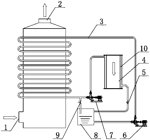
[0019] A pyrolysis gasification furnace heat conduction oil flue gas heating device, comprising a heating furnace tower body and a cooling furnace, the cooling furnace is provided with a cooling furnace outlet flue 4, and the outer ring of the cooling furnace outlet flue 4 is provided with a jacket 10, The lower part of the heating furnace tower body is provided with a saturated flue gas inlet 1, the top of the heating furnace tower body is provided with an unsaturated flue gas outlet 2, and the heating furnace tower body is provided with a heat conduction oil pipeline 3, and one end of the heat conduction oil pipeline 3 is connected to the The outlet of the oil pump A6 is connected, the other end of the heat transfer oil pipeline 3 is connected in two ways, one is connected to the inlet of the oil pump B7, the outlet of the oil pum...


PUM


Abstract

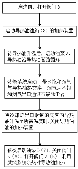
The invention discloses an operation process of a pyrolysis gasifier heat-transfer oil fume heating device. According to the operation process, a saturated fume inlet is arranged at the lower part of the tower body of a heating furnace; an unsaturated fume outlet is arranged at the top of the tower body of the heating furnace; a heat-transfer oil pipeline is arranged in the tower body of the heating furnace; one end of the heat-transfer oil pipeline is connected with the outlet of an oil pump A; the other end of the heat-transfer oil pipeline is divided into two branches for connection; one branch is connected with the inlet of an oil pump B; the outlet of the oil pump B is communicated with the upper part of a clamping sleeve; the other branch is connected into a heat-transfer oil tank through a valve B; the heating device is arranged in the heat-transfer oil tank; the lower part of the heat-transfer oil tank is connected with the inlet of the oil pump A through a pipe I; and the upper part of the heat-transfer oil tank is connected with the lower part of the clamping sleeve through a pipeline II, a valve A and a pipeline III in sequence. The operation process provided by the invention is reasonable in structure, solves the problem that the bag-type dust remover of a conventional pyrolysis gasifier is subjected to bag blockage due to the entrainment of water in fume during a quenching deacidification process, improves the stability and reliability of equipment operation, and has good economic and social benefits in popularization and application.

Description

technical field [0001] The invention belongs to the technical field of garbage pyrolysis gasification incineration, and in particular relates to an operation process of a heat conduction oil flue gas heating device of a pyrolysis gasification furnace. Background technique [0002] The existing pyrolysis gasifier has the problem that after the flue gas is quenched to remove acid, the water vapor entrained in the flue gas will easily cause the bag to stick to the bag, the flue gas cannot pass through the bag filter smoothly and the negative pressure of the bag is not enough, and the operation of the equipment is unstable; while cooling The flue gas in the flue at the furnace outlet is discharged with heat, and the waste heat cannot be effectively utilized, which wastes energy. Contents of the invention [0003] The object of the present invention is to solve the above-mentioned technical problems. [0004] The object of the present invention is achieved in the following way...

Claims


Application Information

Patent Timeline
Patent Type & Authority Patents(China)
IPC IPC(8): F23J15/08
CPCF23J15/08F23J2900/15081
Inventor 王志斌周云峰饶品华刘学军陈和平程永伟
Owner 江苏联兴成套设备制造有限公司
Learn More