Distributed optical fiber monitoring system and monitoring method for seepage velocity in hydraulic structures

A technology of distributed optical fiber and monitoring system, which is applied in the direction of fluid velocity measurement, velocity/acceleration/shock measurement, and measuring devices, etc., which can solve the problems of incomplete reflection of leakage information, missed detection, and difficulty in functioning, etc., to increase contrast reliability and reliability, and the effect of ensuring the contact area

Active Publication Date: 2017-08-15
HOHAI UNIV
View PDF6 Cites 0 Cited by
  • Summary
  • Abstract
  • Description
  • Claims
  • Application Information

AI Technical Summary

Problems solved by technology

[0004] Electrical detection, capacitive sensor and fiber optic grating temperature sensing technology belong to point detection, but the point detection method does not fully reflect the leakage information, and missed detection often occurs; electromagnetic detection and elastic wave detection technology belong to integral detection, Once the overall detection is faced with slightly complicated geological conditions, environmental conditions, and embankment foundation conditions, this type of method may fail and it will be difficult to play a role; distributed optical fiber temperature sensing technology belongs to distributed detection, and distributed detection has the characteristics of distributed detection. Measurement, anti-electromagnetic and high voltage, long-distance, real-time monitoring and many other advantages, but due to the difficulty of its layout and protection, the practical engineering application is not high

Method used


Image

  • Distributed optical fiber monitoring system and monitoring method for seepage velocity in hydraulic structures
  • Distributed optical fiber monitoring system and monitoring method for seepage velocity in hydraulic structures
  • Distributed optical fiber monitoring system and monitoring method for seepage velocity in hydraulic structures

Examples


Embodiment Construction

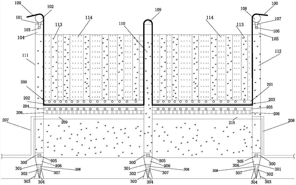
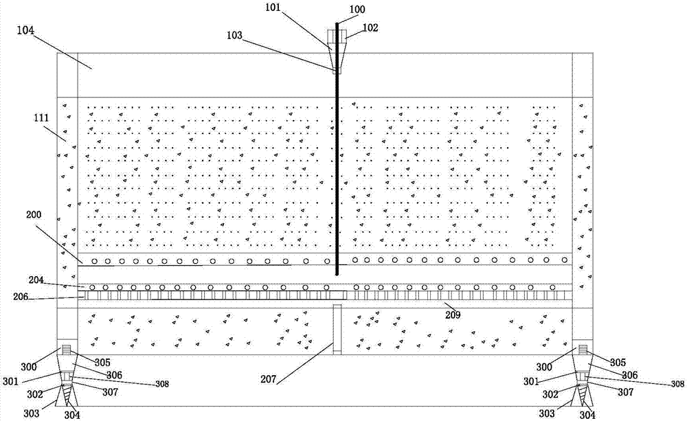
[0024] Such as Figure 1 to Figure 4 as shown in Figure 1 to Figure 4 As shown, a distributed optical fiber monitoring system for seepage flow velocity of a hydraulic structure body of the present invention specifically includes a first soil-rock junction seepage test module, a second soil-rock junction seepage test module, a distributed sensing optical fiber monitoring module, and a soil-rock junction. Joint seepage frame module; distributed sensing optical fiber monitoring module is built in the first soil-rock joint seepage test module and the second soil-rock joint seepage test module, the first soil-rock joint seepage test module and the second soil-rock joint seepage test module Connected by the main frame, the soil-rock joint seepage frame module is distributed at the bottom of the soil-rock joint seepage test module.

[0025] In the present invention, the first soil-rock combination seepage test module includes a 2m-high first frame 111 that constructs the frame stru...


PUM


Abstract

The invention discloses a distributed fiber monitoring system and method for the seepage flow velocity of a hydraulic structural body, and the system comprises a sensing optical fiber, a main frame, a first frame, and a second frame. Concrete and a first medium are respectively disposed between the first frame and the main frame and between the second frame and the main frame in an alternate manner. A flow velocity signal pre-amplifier is disposed below the concrete and the first medium. An optical fiber carrying platform network and a flow velocity induction rod are sequentially disposed below the flow velocity signal pre-amplifier. The flow velocity induction rod is connected with a seeped water temporary storage pool through a flow guide fine tube. The seeped water temporary storage pool is communicated with the outside through a water overflowing pipe. The sensing optical fiber enters the optical fiber carrying platform network along an inner wall of the first frame, then passes by the main frame to enter the optical fiber carrying platform network again, and comes out from an inner wall of the second frame. The system and method are quick, simple, efficient and precise, and effectively improve the effect of monitoring the seepage flow velocity of the hydraulic structural body.

Description

technical field [0001] The invention relates to a distributed optical fiber monitoring system and a monitoring method for seepage flow velocity of a hydraulic structure body, and belongs to the monitoring technology for potential safety hazards of a hydraulic structure body. Background technique [0002] The seepage of hydraulic structures is an important factor affecting the safety of the project. Using reliable monitoring technology to find and know the seepage location and status in time has attracted more and more attention in the engineering field. With the improvement of the distributed optical fiber sensing theory , The continuous development of various sensors, the application in small projects, and the application in water conservancy and civil engineering today, the superiority of distributed optical fiber sensing technology is becoming more and more reflected, and the engineering application prospects are becoming more and more extensive, but for In the exploratio...

Claims


Application Information

Patent Timeline
Patent Type & Authority Patents(China)
IPC IPC(8): G01P5/26
CPCG01P5/26
Inventor 苏怀智杨孟骆鸿杨勇
Owner HOHAI UNIV
Why Eureka
Try Eureka