Manufacturing method of shape-controllable flexible micro-nano column array

A manufacturing method, micro-nano technology, applied in the direction of nanostructure manufacturing, nanotechnology, nanotechnology, etc., can solve the problems of high manufacturing cost, low output, geometric deformation of nanostructures, etc., to avoid easy fracture, precise controllability, The effect of easy operability

Active Publication Date: 2016-07-20
XI AN JIAOTONG UNIV
View PDF6 Cites 10 Cited by
  • Summary
  • Abstract
  • Description
  • Claims
  • Application Information

AI Technical Summary

Problems solved by technology

[0003] At this stage, the manufacturing process of high aspect ratio polymer micro-nano column arrays has the following problems: the micro-nano column or fiber prepared by electrospinning method has low strength, and it is difficult to obtain nanofiber filaments or short fibers separated from each other, and the yield is very low ; The mechanical pressure introduced by the nanoimprint method will cause problems such as geometric deformation of the nanostructure and uneven filling of the variable-size structure; the electric induction molding method and the mold replica method rely on the template, which is generally obtained by dry etching, and its manufacturing cost In addition, the problem of micro-column breakage is prone to occur during the demoulding process of the mold replica method.
In addition, the existing technology is difficult to realize the fabrication of inclined or complex polymer micro-nano column arrays
These issues severely restrict the functional reliability of devices containing polymeric micro-nanopillar arrays

Method used


Image

  • Manufacturing method of shape-controllable flexible micro-nano column array
  • Manufacturing method of shape-controllable flexible micro-nano column array
  • Manufacturing method of shape-controllable flexible micro-nano column array

Examples


Embodiment 1

[0028] A method for manufacturing a shape-controllable flexible micro-nano pillar array, comprising the following steps:

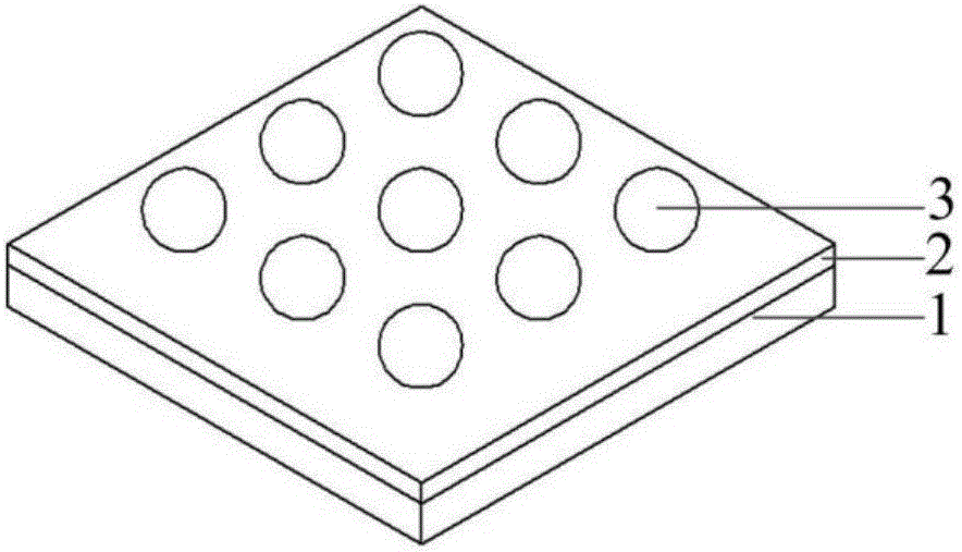
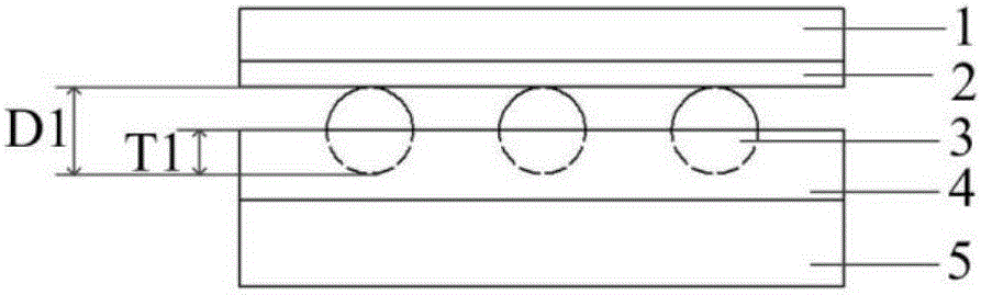
[0029] 1) Refer to figure 1 with figure 2 , first coat the surface of the substrate 1 with a hydrosol adhesion layer 2, then obtain a micro-nano patterned photoresist on the hydrosol adhesion layer 2 through a photolithography process; then obtain the particle size on the surface of the photoresist by scraping D1 = patterning of micro-nanoparticles 3 of 5 μm, and then removing the photoresist to obtain a patterned template of micro-nanoparticles 3, wherein the micro-nanoparticles 3 are spherical polystyrene;

[0030] 2) Refer to figure 2 , coating the polymer 4 on the surface of the substrate 5, and then preheating the substrate 5, the preheating parameters: the temperature is 60°C, the time is 10 minutes, the polymer 4 is PDMS (polydimethylsiloxane) ;

[0031] 3) Refer to figure 2 , contacting and embedding the micronanoparticles 3 on the surface ...

Embodiment 2

[0036] A method for manufacturing a shape-controllable flexible micro-nano pillar array, comprising the following steps:

[0037] 1) Coating a hydrosol adhesion layer 2 on the surface of the substrate 1 first, and then obtaining a micro-nano patterned photoresist on the hydrosol adhesion layer 2 through a photolithography process; Patterning of micro-nanoparticles 3 with a diameter D2=10 μm, and then removing the photoresist to obtain a patterned template of micro-nanoparticles 3, where the micro-nanoparticles 3 are cubic indium trioxide;

[0038] 2) Coating the polymer 4 on the surface of the substrate 5, and then preheating the substrate 5, the preheating parameters: the temperature is 75°C, the time is 6 minutes, and the polymer 4 is PS (polystyrene);

[0039] 3) Refer to Image 6 (a), contacting and embedding the micronanoparticles 3 on the surface of the patterned template into the polymer 4, the embedding depth T2=5 μm;

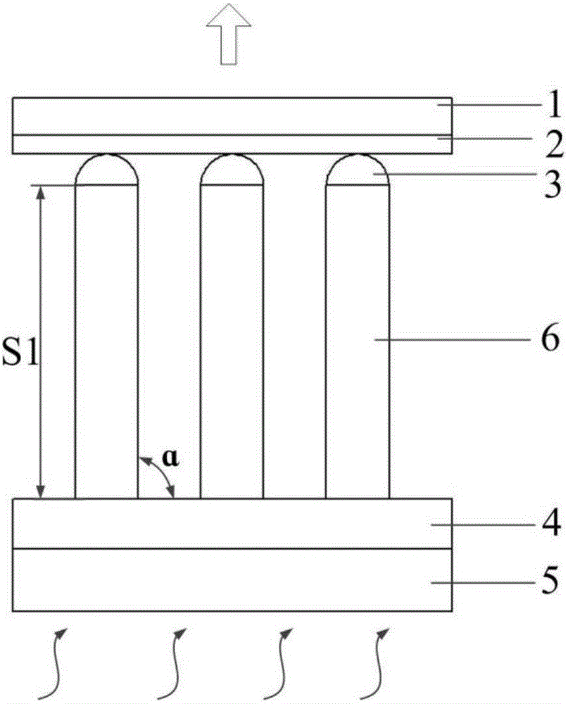
[0040] 4) Refer to Image 6 (b), pull the patt...

Embodiment 3

[0044] A method for manufacturing a shape-controllable flexible micro-nano pillar array, comprising the following steps:

[0045] 1) Refer to Figure 7 (a), first coat the hydrosol adhesive layer 2 on the surface of the substrate 1, then obtain the micro-nano patterned photoresist on the hydrosol adhesive layer 2 by a photolithography process; then pass the scraping method on the photoresist surface Obtain the patterning of micro-nano particles with a 3-shaped pattern of particle diameter D3=200 μm; remove the photoresist to obtain a patterned template of 3-shaped micro-nano particles, and the micro-nano particles 3 are columnar sodium chloride;

[0046] 2) Coating the polymer 4 on the surface of the substrate 5, and then preheating the substrate 5, the preheating parameters: the temperature is 90°C, the time is 2 minutes, and the polymer 4 is PTT (polyurethane);

[0047] 3) Refer to Figure 7 (b), contacting and embedding the micro-nano particles 3 on the surface of the pat...


PUM

PropertyMeasurementUnit
particle diameteraaaaaaaaaa

Abstract

Disclosed is a manufacturing method of a shape-controllable flexible micro-nano column array.The manufacturing method includes: coating a hydrosol adhesion layer on the surface of a substrate, obtaining a micro-nano graphical photoresist on the hydrogel adhesion layer through a photoetching process, obtaining micro-nano graphical particles on the surface of the photoresist through a scraping-coating method, and removing the photoresist to obtain a graphical template of the micro-nano particles; coating a polymer on the surface of the substrate, and pre-heating the substrate; enabling the micro-nano particles on the surface of the graphical template to contact with and to be embedded in the polymer; lifting the graphical template to enable the polymer to be drawn to be a micro-nano column array, and heating the substrate to solidify the micro-nano column array; heating the graphical template to enable the micro-nano particles to break away from the hydrogel adhesion layer to obtain a micro-nano column array with the micro-nano particles at the top end; removing the micro-nano particles at the top end of the micro-nano column array to obtain a polymer micro-nano column array.The manufacturing method has the advantages of simple operation, low cost and short period.

Description

technical field [0001] The invention belongs to the technical field of micro-nano manufacturing, and in particular relates to a method for manufacturing a shape-controllable flexible micro-nano column array. Background technique [0002] High-aspect-ratio polymer micro-nanopillar arrays have large specific surface area and good electromagnetic wave modulation ability, and are widely used in the enhanced absorption of electrons in solar cells, cell inspection and particle separation in the biological field, functional coatings (superhydrophobic and superoleophobic) ), microfluidic chips and other fields. At present, the preparation methods of high-aspect-ratio polymer micro-nano-column arrays mainly include: electrospinning, nanoimprinting, electrical induction molding, and mold replicating. Among them, the electrospinning method refers to the process in which a polymer solution (or melt) forms fibers under the action of a high-voltage electric field. Its core is to make the...

Claims


Application Information

Patent Timeline
Patent Type & Authority Applications(China)
IPC IPC(8): B82B3/00B82Y40/00B81C1/00
CPCB81C1/00B82B3/00B82B3/0004B82Y40/00
Inventor 蒋维涛刘红忠雷彪陈邦道史永胜尹磊
Owner XI AN JIAOTONG UNIV
Why Eureka
Try Eureka