
Self-blocking sub-module with energy-consuming resistor and application thereof

An energy-dissipating resistor and sub-module technology is applied in electrical components, output power conversion devices, and irreversible DC power input to AC power output. control device and other problems, to achieve the effect of reducing the time constant

Inactive Publication Date: 2016-07-13
HUAZHONG UNIV OF SCI & TECH
View PDF5 Cites 12 Cited by
  • Summary
  • Abstract
  • Description
  • Claims
  • Application Information

AI Technical Summary

Problems solved by technology

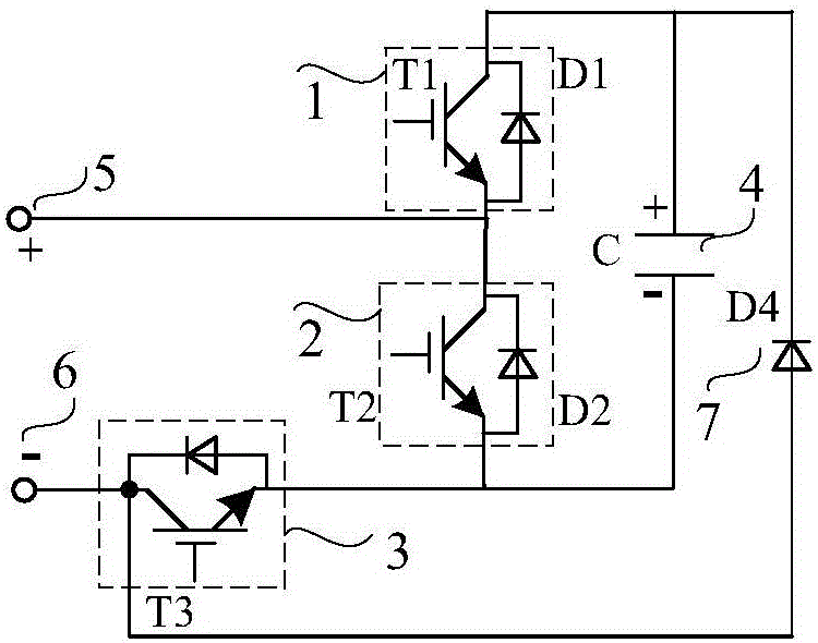
But before the fault current drops to zero, the fault current flows through D1, C, and D4, and continues to charge the DC capacitor C, causing the voltage of the DC capacitor to rise
[0005] When the self-resistance type sub-module is used for intermediate frequency MMC (such as 200Hz-500Hz MMC), since the capacitance of the intermediate frequency MMC sub-module and the inductance of the bridge arm are small, the charging of the DC capacitor voltage will cause the voltage of the DC capacitor to rise quickly. When the value is high, the full-control device of the sub-module will be subjected to high voltage, which may damage the full-control device, thereby threatening the safe operation of the system. Therefore, certain measures must be taken to suppress the rise of the DC capacitor voltage

Method used


Image

  • Self-blocking sub-module with energy-consuming resistor and application thereof
  • Self-blocking sub-module with energy-consuming resistor and application thereof
  • Self-blocking sub-module with energy-consuming resistor and application thereof

Examples


Embodiment Construction

[0035] In order to make the object, technical solution and advantages of the present invention clearer, the present invention will be further described in detail below in conjunction with the accompanying drawings and embodiments. It should be understood that the specific embodiments described here are only used to explain the present invention, not to limit the present invention. In addition, the technical features involved in the various embodiments of the present invention described below can be combined with each other as long as they do not constitute a conflict with each other.

[0036] According to the sub-module topology provided by one embodiment of the present invention, it is preferably used to construct novel modular multilevel converters and DC-DC transformers, so that the novel modular multilevel converters and DC-DC transformers can be used in two In terminal DC transmission, multi-terminal DC transmission and DC power grid, its remarkable technical performance ...


PUM


Abstract

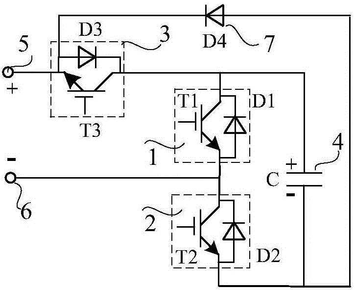
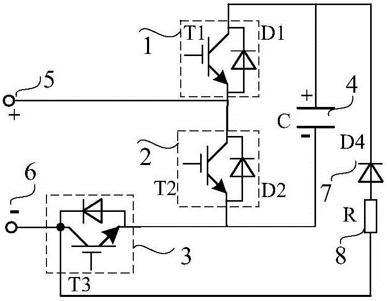
The invention discloses a self-blocking sub-module topological structure with an energy-consuming resistor. The sub-module topological structure comprises two switch modules connected in series, a DC capacitor, a third switch module, a diode, and the energy-consuming resistor. Each of the two switch modules is composed of a full-controlled device and a diode in inverse parallel connection. The negative end of the first switch module is connected with the positive end of the second switch module. The positive pole and the negative pole of the DC capacitor are connected with the positive end of the first switch module and the negative end of the second switch module respectively. The third switch module is electrically connected with the first switch module or the second switch module. The diode is electrically connected with the third switch module and the DC capacitor. The energy-consuming resistor and the diode are connected in series to form a series connection assembly. The invention further discloses a modular multi-level converter containing the self-blocking sub-module topological structure. The self-blocking sub-module topological structure may inhibit an increase in the voltage of a sub-module DC capacitor for the duration of blocking a DC fault, and guarantees system operation safety.

Description

technical field [0001] The invention belongs to the technical field of electric power transmission and distribution, and more specifically relates to a self-resistance sub-module topology and a hybrid converter with the self-resistance sub-module topology. Background technique [0002] Self-blocking sub-module (Self-blocking Sub-module) is a new type of modular multilevel converter sub-module topology, the modular multilevel converter (MMC) composed of it has the ability to block DC fault current Function, suitable for overhead line DC transmission occasions. [0003] Currently recognized modular multilevel converter sub-modules include half-bridge sub-modules, full-bridge sub-modules and clamped double-type sub-modules. The MMC composed of half-bridge sub-modules does not have the ability to block the DC fault current. When a DC fault occurs, it is necessary to open the AC circuit breaker or rely on the DC circuit breaker to cut off the DC fault path. This method reduces t...

Claims


Application Information

Patent Timeline
IPC IPC(8): H02M7/537H02M7/49H02M1/32
CPCH02M1/32H02M7/49H02M7/537H02M7/4835
Inventor 林卫星向往文劲宇
Owner HUAZHONG UNIV OF SCI & TECH
Learn More