Electronic frequency shift simulator for laser velocity measurement sensor

A laser speed measurement and sensor technology, applied in the testing/calibration of speed/acceleration/shock measurement equipment, instruments, measuring devices, etc., can solve the problem of difficult to find moving targets and test equipment, high precision requirements for landing navigation measurement, and speed measurement simulation Problems such as difficulty in device design, etc., to achieve the effect of small error, simple structure and high precision

Inactive Publication Date: 2016-07-13
SHANGHAI INST OF TECHNICAL PHYSICS - CHINESE ACAD OF SCI
View PDF0 Cites 7 Cited by
  • Summary
  • Abstract
  • Description
  • Claims
  • Application Information

AI Technical Summary

Problems solved by technology

[0003] Compared with microwaves, lasers have shorter wavelengths, higher velocity measurement accuracy and velocity measurement resolution, but larger Doppler frequency shifts and wider frequency ranges; at the same time, velocity belongs to vector information, which needs to be measured in three directions and then synthesized. Doppler shift due to velocity is very difficult to simulate in the laboratory
During the landing process, the range of motion speed of the probe is very large, and landing navigation requires high speed measurement accuracy. It is difficult to find a suitable moving target and test equipment for actual measurement, which makes the design of the speed measurement simulator more difficult.
[0004] In the indoor simulation test of the spaceborne laser speed sensor with a speed range from -20m / s to 100m / s, and to make the simulated speed measurement accuracy better than 0.1%v, there is no corresponding technology in the published literature Program

Method used


Image

  • Electronic frequency shift simulator for laser velocity measurement sensor
  • Electronic frequency shift simulator for laser velocity measurement sensor
  • Electronic frequency shift simulator for laser velocity measurement sensor

Examples


Embodiment Construction

[0025] The specific embodiment of the present invention is described in further detail below in conjunction with accompanying drawing:

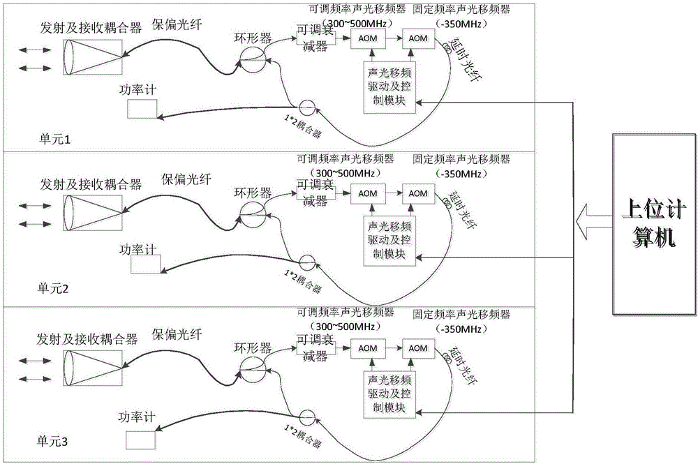
[0026] The present invention is composed of three analog channels, which respectively correspond to the three velocity vector channels of the laser speed measuring sensor. The hardware of the three channels is consistent. The following only describes one channel:

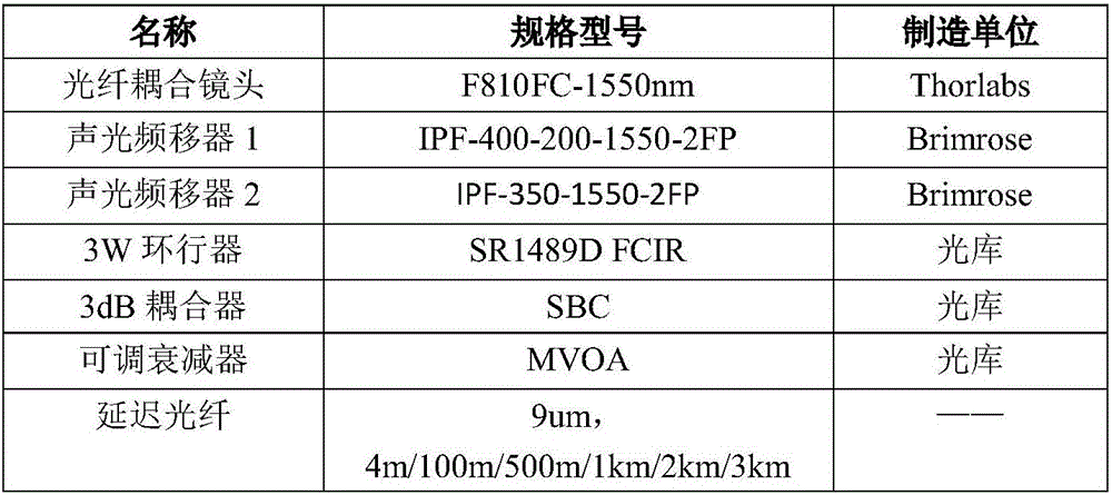
[0027] The transmitting and receiving modules consist of fiber couplers and single-mode polarization-maintaining fibers. The fiber optic coupler is F810FC-1550 from Thorlabs in the United States, with a focal length of 37.13 mm, a numerical aperture of 0.24, an entrance pupil of 8.91 mm, and a convergent spot diameter of 10.3 μm. The single-mode polarization-maintaining fiber adopts CorningPMFibersPI936 of the optical library, the core diameter is 9μm, and the accepted power is greater than 3W.

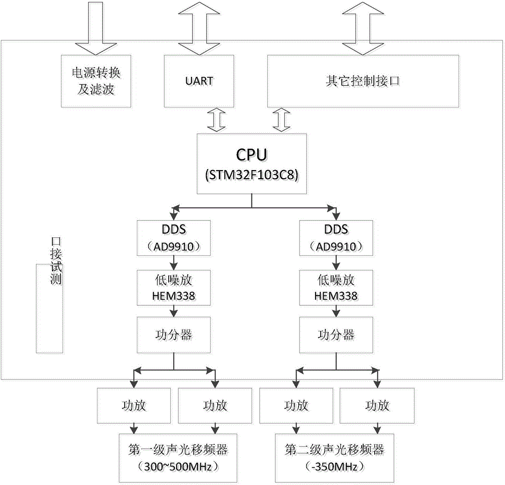
[0028] The electric control box includes an electronic frequency shift function modul...


PUM


Abstract

The invention discloses an electronic frequency shift simulator for a laser velocity measurement sensor. The simulator is formed by three same units which are respectively corresponding to three velocity vector channels of the laser velocity measurement sensor, and control and interaction are performed on the three units by a computer software system. The electronic frequency shift simulator receives a laser emitted by the laser velocity measurement sensor by an emission and reception coupler, the laser is coupled to optical fibers of an optical fiber circulator, the laser outputted by the optical fiber circulator reaches a two-stage acousto-optic frequency shifter via an adjustable attenuator, the frequency-shifted laser signal is divided into two parts by the coupler, one part is used for power monitoring, the other part is emitted via delayed optical fibers and the circulator and is received by the laser velocity measurement sensor to perform speed measurement. According to the invention, the simulator has advantages that the range of the simulated frequency shift is large and the precision is high, so that a great convenience is brought to laboratory test of the laser velocity measurement sensor.

Description

technical field [0001] The invention relates to a speed simulator of a laser speed measuring sensor, in particular to a speed measuring simulator using electronics to simulate speed frequency shift, which is used to detect the speed measuring range and speed measuring accuracy of a laser speed measuring sensor. Background technique [0002] Using unmanned probes to land on the surface of target celestial bodies such as the moon, Mars or asteroids for on-site exploration and even sample return is an important way for human beings to explore the universe, and it is also one of the hot spots for the development of deep space exploration activities in the future. Launching satellites or probes to perform soft landing on the surface of other planets is an important direction for space exploration. Accurate velocity measurement is a key factor for a spacecraft to select an accurate landing site to achieve a safe and soft landing. [0003] Compared with microwave, laser has shorte...

Claims


Application Information

Patent Timeline
Patent Type & Authority Applications(China)
IPC IPC(8): G01P21/02
CPCG01P21/02G01S7/497
Inventor 程鹏飞卜弘毅舒嵘黄庚华
Owner SHANGHAI INST OF TECHNICAL PHYSICS - CHINESE ACAD OF SCI
Why Eureka
Try Eureka