
Special protector and method for speed reducer of downhole electric submersible progressing cavity pump

A technology of reducer and screw pump, which is applied in pumps, pump components, earthwork drilling, etc., can solve problems such as failure to popularize and apply, downhole reducer failure, poor lubrication, etc., to increase effective production days, reduce operating costs, The effect of prolonging the pump inspection period

Active Publication Date: 2016-07-13
东营凯维石油科技有限责任公司
View PDF5 Cites 4 Cited by
  • Summary
  • Abstract
  • Description
  • Claims
  • Application Information

AI Technical Summary

Problems solved by technology

However, ground-driven screw pumps have not been popularized and applied because the driving rod is easy to cause problems such as rod breakage, rod tube wear, and rod jamming.
[0004] However, the existing downhole electric submersible screw pumps have the practical problems of large reverse thrust and premature failure of the thrust bearing. At present, people are trying to transmit the axial force to the shell and the connection method step by step through the multi-stage series bushings on the periphery of the shaft. on the flange to offset the axial force and transmit the output torque without axial force to the shaft end spline sleeve
However, the existing electric submersible screw pump reducer protector can only store a certain amount of lubricating oil. Due to the limitation of underground space, the storage capacity is limited and cannot meet the needs of long-term continuous operation of the submersible screw pump unit. It is often caused by poor lubrication. Downhole reducer fails prematurely

Method used


Image

  • Special protector and method for speed reducer of downhole electric submersible progressing cavity pump
  • Special protector and method for speed reducer of downhole electric submersible progressing cavity pump
  • Special protector and method for speed reducer of downhole electric submersible progressing cavity pump

Examples


Embodiment Construction

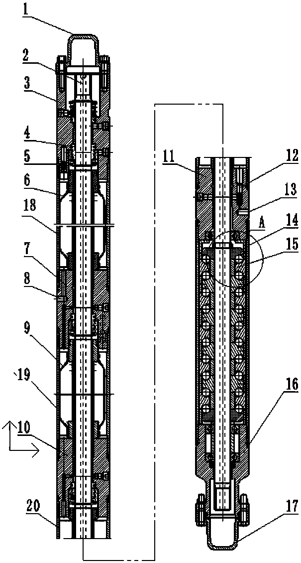
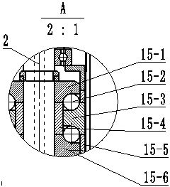
[0026] combined with Figure 1-3 , to further describe the present invention:

[0027] A special protector for downhole electric submersible screw pump reducer mentioned in the present invention, including an upper transport cap 1, a hollow main shaft 2, a head assembly 3, a mechanical seal assembly 4, an oil drain valve assembly 5, and an upper capsule 6 , upper guide body 7, breathing hole 8, lower capsule 9, middle guide body 10, lower guide body assembly 11, high-pressure check valve assembly 12, oil filling joint hole 13, lower housing 14, thrust bearing group 15, base Assembly 16, lower transportation cap 17, upper casing 18, middle casing 19 and connecting pipe 20, the upper transportation cap 1 is movably connected with the head assembly 3, and the hollow main shaft 2 is fixed inside the head assembly 3, And the bottom of the head assembly 3 cooperates with the hollow main shaft 2 through the mechanical seal assembly 4; The bottom of 18 is connected to the upper guid...


PUM


Abstract

The invention relates to a special protector and a method for a speed reducer of a downhole electric submersible progressing cavity pump.The method includes that new lubricating oil is delivered into downhole environments via a special oil injection cable by a high-pressure oil injection pump on the ground, a check safety valve is arranged at the lower end of the special protector, starting pressures of the check safety valve can be adjusted according to different well depths, the check safety valve is started under the effects of oil pressures, the new lubricating oil is injected into the special protector from the lower portion, and old lubricating oil is drained into clearance of oil casings via a breathing hole in the upper portion of the special protector, so that an oil change procedure can be completed.The special protector and the method have the advantages that the special protector is high in original protector compatibility, and most accessories are universal; the special protector is simple in structure, and the starting pressures of the check safety valve can be adjusted according to the different well depths; the special protector can be easily and reliably connected with the oil injection cable; the lubricating oil can be changed periodically, accordingly, the downhole speed reducer can be assuredly excellently lubricated, and the service life of the speed reducer can be effectively prolonged; the thrust bearable capacity can be enhanced; the pump checking cycle can be prolonged, and the operating expense can be reduced.

Description

technical field [0001] The invention relates to an underground electric submersible screw pump, in particular to a special protector and method for the reducer of the underground electric submersible screw pump. Background technique [0002] Electric SubmersibleProgressingCavityPum (ESPCP) is a combination of Progressive Cavity Pump (PCP) and Electric Submersible Pump (ESP). With the gradual deepening of oilfield development, the proportion of heavy oil, sandy, medium and low production wells is increasing day by day. The traditional beam pumping unit will have pump jams, rod jams, pump wear, and pumping problems due to thick oil and sand production. Oil rod breakage and other situations lead to frequent oil well operations or even shutdown. Seeking new oil recovery technology has become the only way for the further development of oilfields. The screw pump is suitable for discharging viscous liquid and liquid containing solid phase, and the flow rate is uniform and stable....

Claims


Application Information

Patent Timeline
Patent Type & Authority Applications(China)
IPC IPC(8): F04C15/00
CPCE21B43/128F04C2/107F04C13/008F04C15/00F04C15/0042F04C15/0061F04C15/0088
Inventor 马力齐顺亭
Owner 东营凯维石油科技有限责任公司
Learn More