


Quick Research
Generate reliable direction feasibility study reports for your R&D in just a few steps.

Technical Q&A
Discover and master advanced knowledge NOW. Basics, ideas, possibilities, all at once.

Find Solutions
As an expert in R&D theories, this can generate solutions to your technical problems instantly.

Evaluate Feasibility
Analyze your overall solution with one click, know your potential R&D risks in advance.

Monitor Landscape
Get weekly tech updates, stay abreast of the latest tech innovations and key insights.
Device and method using pulse accumulation and amplification to realize high power ultrashort pulse laser
An ultrashort pulse laser and pulse stacking technology, which is applied in lasers, laser components, phonon exciters, etc., can solve the problems of fiber amplifier mode instability, spectrum narrowing, and inability to obtain high-power ultrashort pulses
- Summary
- Abstract
- Description
- Claims
- Application Information
AI Technical Summary
Problems solved by technology
Method used
Image

Examples
Embodiment 1
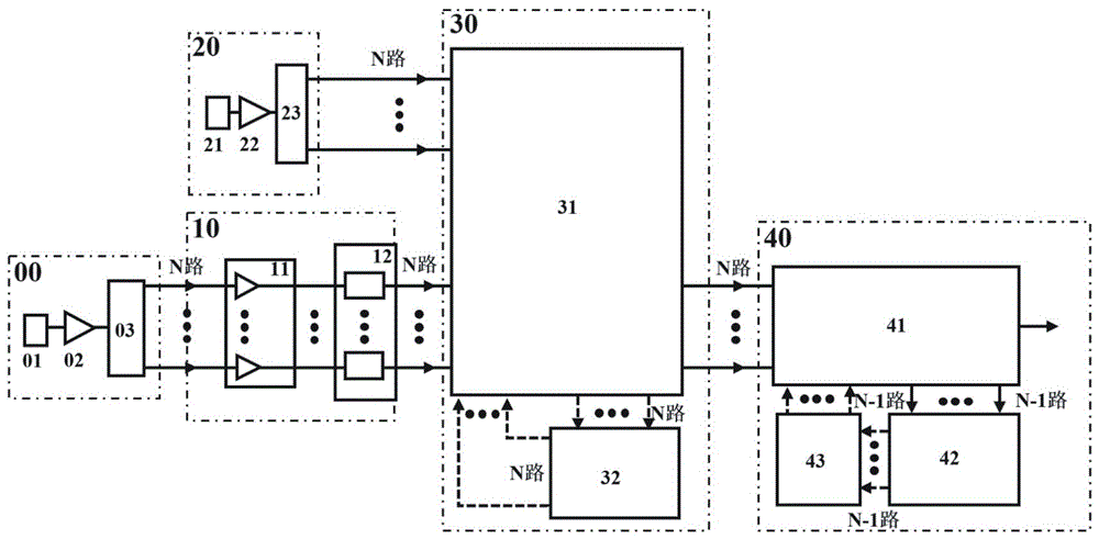
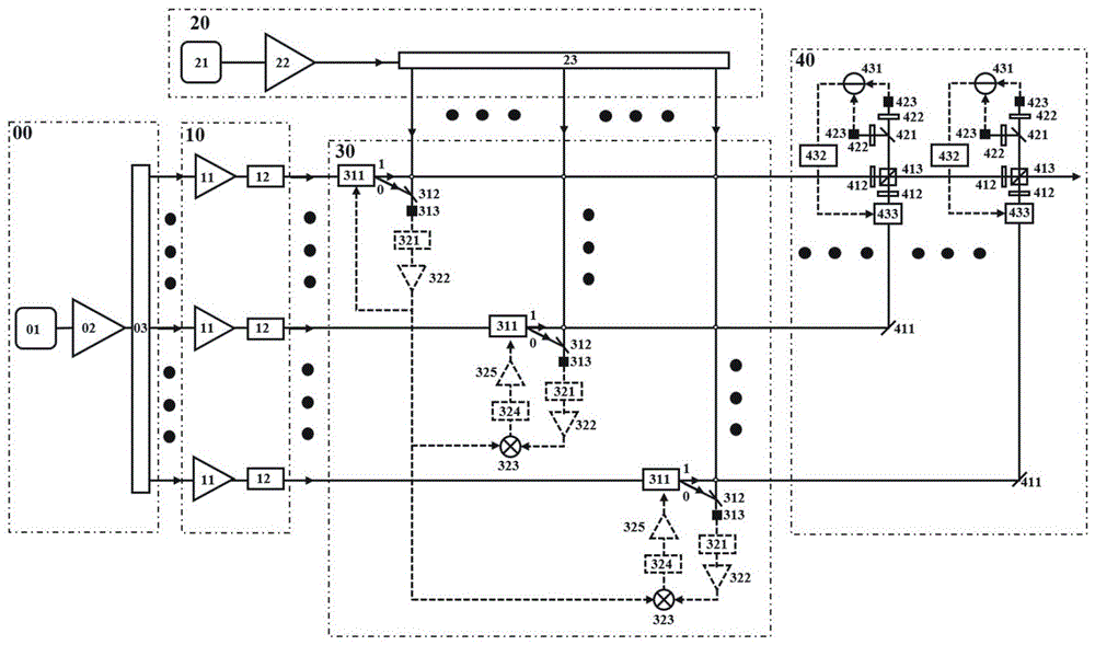
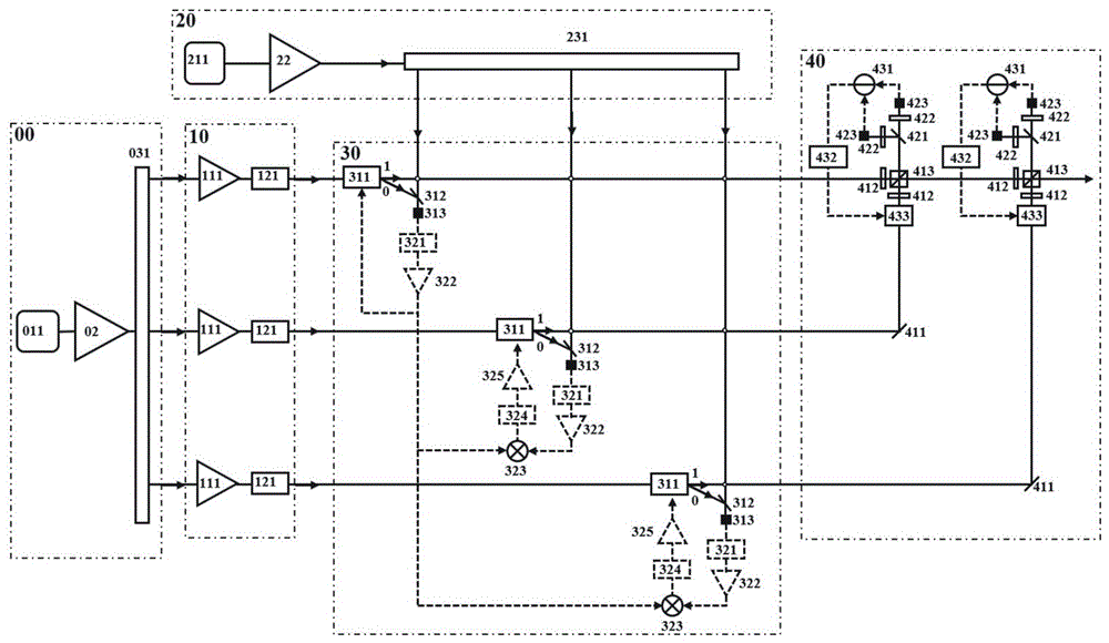
[0034] refer to figure 1 , figure 2 , image 3 In this embodiment, the first laser 01 in the pulse laser beam splitting system 00 selects the ytterbium-doped fiber mode-locked laser 011, the pulse laser beam splitting module 03 selects the fiber beam splitting module 031, and the amplifier module 11 selects three ytterbium-doped fiber chirped pulses The amplifier 111 and the compressor module 12 select three grating compressors 121; the second laser 21 in the continuous laser beam splitting system 20 selects a 1030nm narrow linewidth continuous laser 211, and the laser beam splitting module 23 selects an optical fiber splitting module 231;
[0035] Through the combination of Ytterbium-doped fiber mode-locked laser 011, Ytterbium-doped fiber chirped pulse amplifier 111 and 1030nm narrow-linewidth continuous laser 211, three-way pulse stacking amplification is realized, and high-power ultrashort pulse laser output in the 1030nm band is output.
[0036] The specific working pr...
Embodiment 2
[0043] refer to figure 1 , figure 2 , Figure 4 In this embodiment, the first laser 01 in the pulsed laser beam splitting system 00 selects the erbium-doped fiber mode-locked laser 012, the pulse laser beam splitting module 03 selects the spatial beam splitting module 032, and the amplifier module 11 selects four erbium-doped optical fiber chirped pulses The amplifier 112 and the compressor module 12 select four dispersion compensation optical fiber compressors 122;
[0044] The second laser 21 in the continuous laser beam splitting system 20 is a 1550nm narrow linewidth continuous laser 212, and the laser beam splitting module 23 is a spatial beam splitting module 232;
[0045] Through the combined setting of the erbium-doped fiber mode-locked laser 012, the erbium-doped fiber chirped pulse amplifier 112 and the 1550nm narrow-linewidth continuous laser 212, the four-way pulse stacking amplification is realized, and the 1550nm band high-power ultrashort pulse laser is outpu...
Embodiment 3
[0053] refer to figure 1 , figure 2 , Figure 5 , the pulse amplification system 10 of this embodiment is composed of an amplifier module 11 and a compressor module 12. The amplifier module 11 selects three self-similar amplifiers 113 managed by pulse pre-chirp, and the compressor module 12 selects three prism compressors 123;
[0054] Through the setting of the self-similar amplifier 113 managed by the pulse pre-chirp, three-way wide-spectrum and high-power near-infrared pulse lasers can be realized, so as to pass through the carrier envelope phase synchronization system 30 and the balanced optical cross-correlation pulse stacking amplification system 40 in sequence. Output broad-spectrum high-power near-infrared ultrashort pulse laser.
[0055] The specific working process is as follows:
[0056] In the pulsed laser beam splitting system 00, the pulsed laser beam emitted by the first laser 01 passes through the pre-amplifier 02, and then the pulsed laser beam splitting m...
PUM
 Abstract
Description
Claims
Application Information
 - R&D Engineer
- R&D Manager
- IP Professional
- Industry Leading Data Capabilities
- Powerful AI technology
- Patent DNA Extraction
Browse by: Latest US Patents, China's latest patents, Technical Efficacy Thesaurus, Application Domain, Technology Topic, Popular Technical Reports.
© 2024 PatSnap. All rights reserved.Legal|Privacy policy|Modern Slavery Act Transparency Statement|Sitemap|About US| Contact US: help@patsnap.com