Cylindrical workpiece spring clamping device used for linear cutting

A cylindrical workpiece and spring clamping technology, applied in the field of machining, can solve the problems of precision requirements affecting dimensional accuracy and geometric tolerance, easy deformation, poor rigidity, etc. long life effect

Inactive Publication Date: 2016-07-06
XIAN ZHIYUE ELECTROMECHANICAL TECH
View PDF0 Cites 9 Cited by
  • Summary
  • Abstract
  • Description
  • Claims
  • Application Information

AI Technical Summary

Problems solved by technology

When using a wire cutting machine tool to process a thin-walled cylinder, it is necessary to use a clamping device to tighten the thin-walled cylinder. At that time, because the thin-walled cylinder has the characteristics of thin wall, poor rigidity and weak strength, it is easy to deform during the clamping process. Thus affecting the accuracy requirements of its dimensional accuracy and shape and position tolerance

Method used


Image

  • Cylindrical workpiece spring clamping device used for linear cutting
  • Cylindrical workpiece spring clamping device used for linear cutting

Examples


Embodiment Construction

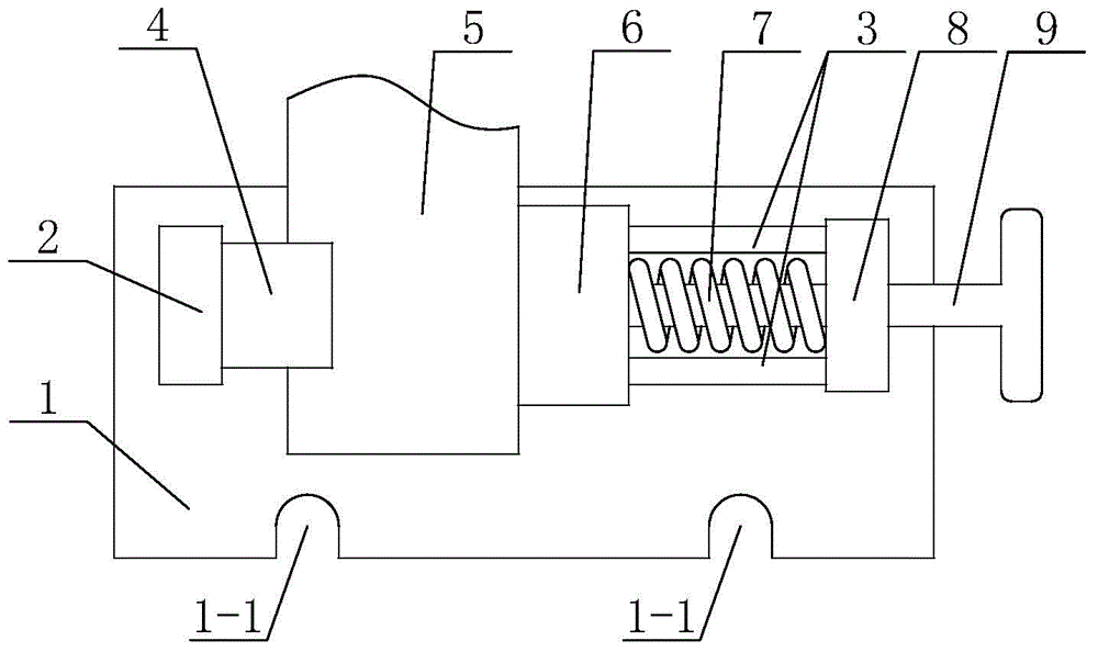
[0022] like figure 1 and figure 2 The shown spring clamping device for a cylindrical workpiece for wire cutting includes a base plate 1 with an open fixing groove 1-1 on one side, and a V-groove pad 4 and a V-groove pad 4 and A sliding head 6, two smooth bars 3 parallel to each other and used to support the sliding head 6, a compression spring 7 for driving the sliding T-shaped pull rod 9 for tightening spring 7; both ends of the upper side of the bottom plate 1 are respectively fixed with a pad support 2 and a pull rod support 8, and the cushion support 2 and the pull rod support 8 are fixedly installed There are two smooth bars 3 , the V-groove pad 4 is fixedly installed on the inner side of the upper end of the pad support 2 , and the sliding pressure head 6 is slidably installed on the two smooth bars 3 . The T-shaped pull rod 9 is slidably installed in the middle of the pull rod support 8 through a light hole. The compression spring 7 is sleeved between the tie rod su...


PUM


Abstract

The invention discloses a cylindrical workpiece spring clamping device used for linear cutting. The cylindrical workpiece spring clamping device comprises a base plate, a V-shaped groove cushion table, a sliding pressing head, unthreaded rods, a pressure spring and a T-shaped pull rod. A cushion table support and a pull rod support are fixedly installed at the two ends of the upper side of the base plate correspondingly. The two unthreaded rods are fixedly installed between the cushion table support and the pull rod support. The V-shaped groove cushion table is fixedly installed on the inner side of the upper end of the cushion table support. The sliding pressing head is slidably installed on the two unthreaded rods. The T-shaped pull rod is slidably installed in the middle of the pull rod support through an unthreaded hole. The end of the T-shaped pull rod is fixedly connected with the sliding pressing head. The portion, located between the sliding pressing head and the pull rod support, of the T-shaped pull rod is sleeved with the pressure spring. The cylindrical workpiece spring clamping device has the following characteristics that the design is reasonable, the structure is simple, the machining accuracy is high, the workpiece assembling and disassembling efficiency is high, the labor intensity of workers is low, maintenance is easy, and the application range is wide.

Description

technical field [0001] The invention belongs to the technical field of machining and relates to a clamp, in particular to a clamping device used for machining a cylindrical workpiece by a wire cutting machine. Background technique [0002] The wire-cut electric discharge machine was invented in the Soviet Union in 1960. Because the wire-cutting process is suitable for the processing of high hardness, difficult-to-machine materials and complex cavities, it plays a very important role in manufacturing, especially mold processing. When using a wire cutting machine to process a thin-walled cylinder, it is necessary to use a clamping device to tighten the thin-walled cylinder. At that time, because the thin-walled cylinder had the characteristics of thin wall, poor rigidity and weak strength, it was easily deformed during the clamping process. As a result, the accuracy requirements of its dimensional accuracy and geometric tolerance are affected. SUMMARY OF THE INVENTION [00...

Claims


Application Information

Patent Timeline
IPC IPC(8): B23H11/00B23H7/02
Inventor 黄冰
Owner XIAN ZHIYUE ELECTROMECHANICAL TECH
Why Eureka
Try Eureka