


Quick Research
Generate reliable direction feasibility study reports for your R&D in just a few steps.

Technical Q&A
Discover and master advanced knowledge NOW. Basics, ideas, possibilities, all at once.

Find Solutions
As an expert in R&D theories, this can generate solutions to your technical problems instantly.

Evaluate Feasibility
Analyze your overall solution with one click, know your potential R&D risks in advance.

Monitor Landscape
Get weekly tech updates, stay abreast of the latest tech innovations and key insights.
Flexible film brittle failure method
A flexible film and flexible film technology, which is applied in the field of scanning electron microscope sample preparation, can solve the problems of limiting the popularity of the device, force deformation at the film section, and non-concentrated force, so as to facilitate manual operation, increase strain rate, and enhance effect of possibility
- Summary
- Abstract
- Description
- Claims
- Application Information
AI Technical Summary
Problems solved by technology
Method used
Image


Examples
Embodiment 1
[0034] Taking the preparation of the brittle section of the polymer flexible film for scanning electron microscopy as an example, the flexible film is a SPEEK proton exchange membrane.
[0035] First, if figure 1 As shown, prepare a long strip of silicon wafer, the length of the silicon wafer is 1.5cm, the width is 5mm, and the aspect ratio is much greater than 2:1, which meets the restriction conditions, and then pre-cut the silicon wafer on the middle side of the strip with a glass knife. Engraving, to get a silicon wafer with grooves on one side.
[0036] Then prepare the flexible film, cut the polymer flexible film into a size slightly smaller than the long silicon wafer, 1 cm long and 3 mm wide.
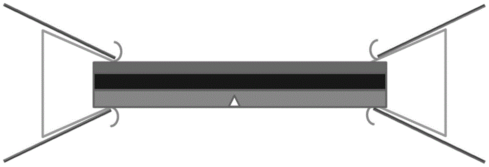
[0037] The third step, such as figure 2 As shown, the polymer flexible film, carbon conductive double-sided adhesive, and silicon wafer are pasted in sequence to form a sandwich structure to form a composite silicon wafer. is the middle layer, and the polymer flexible film is...
Embodiment 2
[0042] Take the brittle section of a polymer flexible film prepared for scanning electron microscopy as an example. The flexible film is a lithium battery separator, made of polypropylene, with many microporous structures, and it is easy to form closed cells by ordinary methods.
[0043] First, if figure 1 As shown, prepare a strip-shaped silicon wafer with a length of 1.5 cm and a width of 5 mm, and then pre-cut one side of the strip in the middle with a glass knife to obtain a silicon wafer with grooves on one side.
[0044] Then prepare the flexible film, cut the polymer flexible film into a size similar to the long silicon wafer, 1 cm long and 3 mm wide.
[0045] The third step, such as figure 2 As shown, the polymer flexible film, carbon conductive double-sided adhesive, and silicon wafer are pasted in sequence to form a sandwich structure to form a composite silicon wafer. It is the middle layer, and the polymer flexible film is the uppermost layer, and then the two ...
Embodiment 3
[0050] Take the brittle section of a polymer flexible film prepared for scanning electron microscopy as an example. The flexible film is polyethylene cling film made of polypropylene, which is relatively flexible at low temperatures.
[0051] First, if figure 1 As shown, prepare a strip-shaped silicon wafer with a length of 1.5 cm and a width of 5 mm, and then pre-cut one side of the strip in the middle with a glass knife to obtain a silicon wafer with grooves on one side.
[0052] Then prepare the flexible film, cut the polymer flexible film into a size similar to the long silicon wafer, 1cm long and 3mm wide.
[0053] In the third step, because polyethylene cling film has good toughness at liquid nitrogen temperature, the above sandwich structure is strengthened, and the pre-grooved silicon wafer, carbon conductive double-sided adhesive, polymer flexible film, carbon conductive double-sided adhesive Silicon wafers are pasted in turn to form a composite silicon wafer, in wh...
PUM
 Abstract
Description
Claims
Application Information
 - R&D Engineer
- R&D Manager
- IP Professional
- Industry Leading Data Capabilities
- Powerful AI technology
- Patent DNA Extraction
Browse by: Latest US Patents, China's latest patents, Technical Efficacy Thesaurus, Application Domain, Technology Topic, Popular Technical Reports.
© 2024 PatSnap. All rights reserved.Legal|Privacy policy|Modern Slavery Act Transparency Statement|Sitemap|About US| Contact US: help@patsnap.com