
Method for conducting cutting blanking on cylindrical steel

A steel and cylindrical technology, applied in the field of auxiliary devices in the cutting process of steel cutting tools, can solve the problems of incision inclination and disadvantage, and achieve the effect of reducing the turning force and increasing the force arm.

Inactive Publication Date: 2016-06-22
黄鸣
View PDF0 Cites 0 Cited by
  • Summary
  • Abstract
  • Description
  • Claims
  • Application Information

AI Technical Summary

Problems solved by technology

In mixed-material cutting tools, cemented carbide is usually used as the cutting edge part of the cutting tool, while hardened steel is used as the main part of the cutting tool, and the cutting edge is welded to the formed cutting tool. Rough grinding, fine grinding, and welding with hard alloy blades form a complete cutting tool workpiece. The cutting process of the cutting tool workpiece is to cut the round steel into segments with a cutting machine. However, the length of the cutting machine’s table is certain. For For larger workpieces, it is easy to incline the incision due to the gravity of the workpiece itself during the cutting process, which is not conducive to the centering of subsequent processing.

Method used


Image

  • Method for conducting cutting blanking on cylindrical steel

Examples


Embodiment

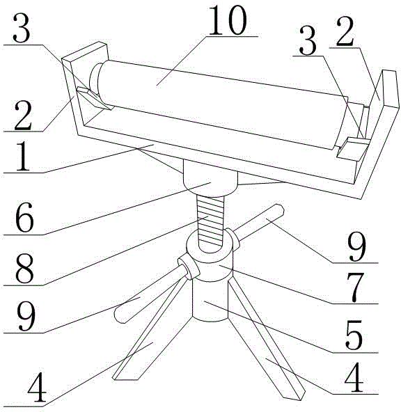
[0017] Such as figure 1 As shown, a method for cutting and blanking cylindrical steel materials in the present invention includes a tripod 4 placed on the ground, a sleeve 5 is fixedly arranged on the axis of the tripod 4, and a sleeve 5 is arranged on the sleeve 5. The rotating cylinder 7 that can rotate around the axis of the sleeve 5 is provided with an internal thread inside the rotating cylinder 7. The rotating cylinder 7 is fixed relative to the sleeve 5 on its axis, and two rotating handles are arranged on the side wall of the rotating cylinder 7. 9. The two rotating handles 9 are located on the same diameter of the rotating cylinder 7, and the lifting screw 8 is set in the rotating cylinder 7 and the sleeve 5, and the top of the lifting screw 8 is set in the holding cylinder 6, and the inside of the holding cylinder 6 is smooth , a flat plate 1 is installed on the top of the holding tube 6, the center of gravity of the flat plate 1 is located on the axis of the holding...


PUM


Abstract

The invention discloses a method for conducting cutting blanking on cylindrical steel. According to the method, a lifting mechanism and a support mechanism are involved. The support mechanism comprises a flat plate. The two ends of the flat plate are each provided with a vertical plate. The two vertical plates are in parallel and installed on the flat plate perpendicularly. The inner sides of the two vertical plates are each provided with a U-shaped trough. A roller is installed in the two U-shaped troughs. The lifting mechanism is installed on a triangular support and connected with the bottom of the flat plate. According to the method for conducting cutting blanking on the cylindrical steel, in the cutting course, the supporting function of two supporting points is always applied to the steel, so that the horizontal position state of the steel is kept, and the defect that in the steel cutting process, due to the function of the gravity of the steel, one end of a workpiece cut is upwards-warped when the cut is deepened, and thus the cut of the cut steel is inclined is overcome. Through the mode that rotary handles are arranged on a rotary barrel, force arms can be added, and rotating force is reduced.

Description

technical field [0001] The invention relates to an auxiliary device in the blanking process of cutting tool steel, in particular to a method for cutting and blanking cylindrical steel. Background technique [0002] Cutting tools are tools used for cutting, mainly referring to turning tools, reamers, planers, drills, etc. There are two main types of materials: cemented carbide and hardened steel. The usual cutting tools are cemented carbide as a whole , the advantage is that the use time is long, the disadvantage is that the cost is too high, and the hard alloy can not be fully utilized; there is also a kind of hardened steel as the basic part of the cutting tool, and the hard alloy is used as the cutting tool blade, the advantage is low cost, the disadvantage is It has short service life, poor wear resistance, complicated processing technology and low success rate. The manufacturing process of cutting tools mainly includes: material selection, blanking, primary processing, ...

Claims


Application Information

Patent Timeline
Patent Type & Authority Applications(China)
IPC IPC(8): B23Q1/76
Inventor 黄鸣
Owner 黄鸣
Learn More