Firearms magazine for rifle length cartridges

Active Publication Date: 2011-10-04
BATTAGLIA VINCENT P
View PDF16 Cites 44 Cited by
  • Summary
  • Abstract
  • Description
  • Claims
  • Application Information

AI Technical Summary

Benefits of technology

[0005]Bearing in mind the problems and deficiencies of the prior art, it is therefore an object of the present invention to provide an improved firearm cartridge magazine that has one or more of the following advantages: 1) effective guiding to the cartridges; 2) protection to the noses of the cartridges; 3) increased magazine strength; 4) increased efficiency in feeding of cartridges into breech; 5) better centerline presentation of the cartridge case to the firearm chamber to enhance the final positioning of the cartridge case shoulder in concentricity to the chamber; and 6) modular configuration to permit cartridges of different sizes to be employed.
[0010]In a further aspect, the firearms magazine comprises opposite side walls defining an interior width sufficient to retain a plurality of firearms cartridges of a first diameter, and a removable insert between the opposite side walls reducing the interior width to retain a plurality of firearms cartridges of a second diameter less than the first diameter.
[0015]In yet another aspect, the firearms magazine comprises opposite side walls defining an interior sufficient to retain a plurality of firearms cartridges, a movable cartridge follower between the opposite side walls for feeding the firearms cartridges out of the magazine and into a gun, and projections extending along at least a portion of a height of the cartridge follower and slideable along the interior of the opposite side walls for preventing tilting of the follower as the cartridges are fed out of the magazine.

Problems solved by technology

The prior art has not effectively protected the tip of the cartridge projectile from dents or flattening of the apex of the tip, resulting in erratic bullet flight and decreased accuracy.
Also, the prior art has not consistently provided exact centerline presentation of the cartridge case to the firearm chamber enhances the seating or final positioning of the cartridge case shoulder in concentricity to the chamber.

Method used


Image

  • Firearms magazine for rifle length cartridges
  • Firearms magazine for rifle length cartridges
  • Firearms magazine for rifle length cartridges

Examples


Embodiment Construction

[0035]In describing embodiments of the present invention, reference will be made herein to FIGS. 1-15 of the drawings in which like numerals refer to like features of the invention.

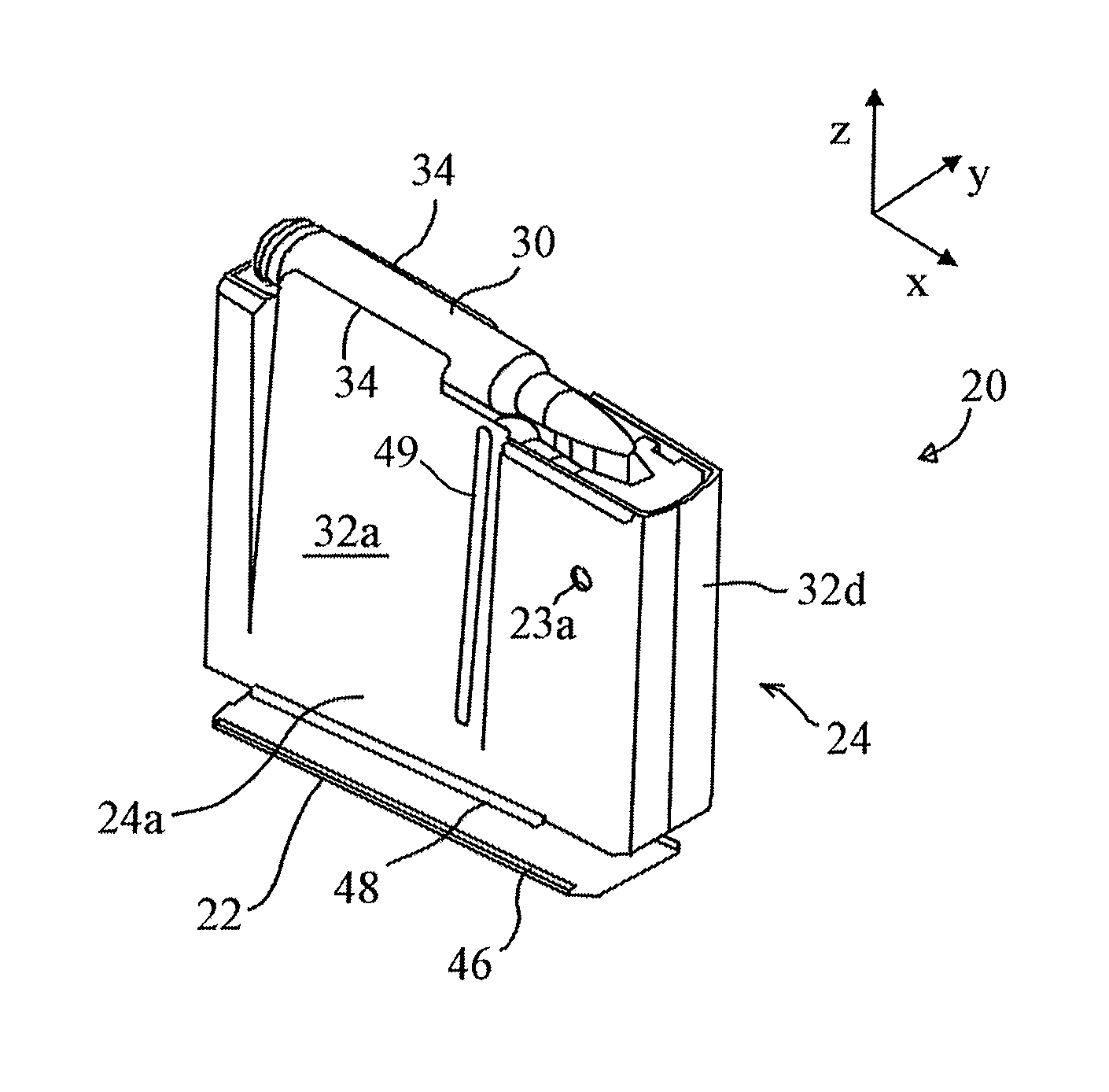
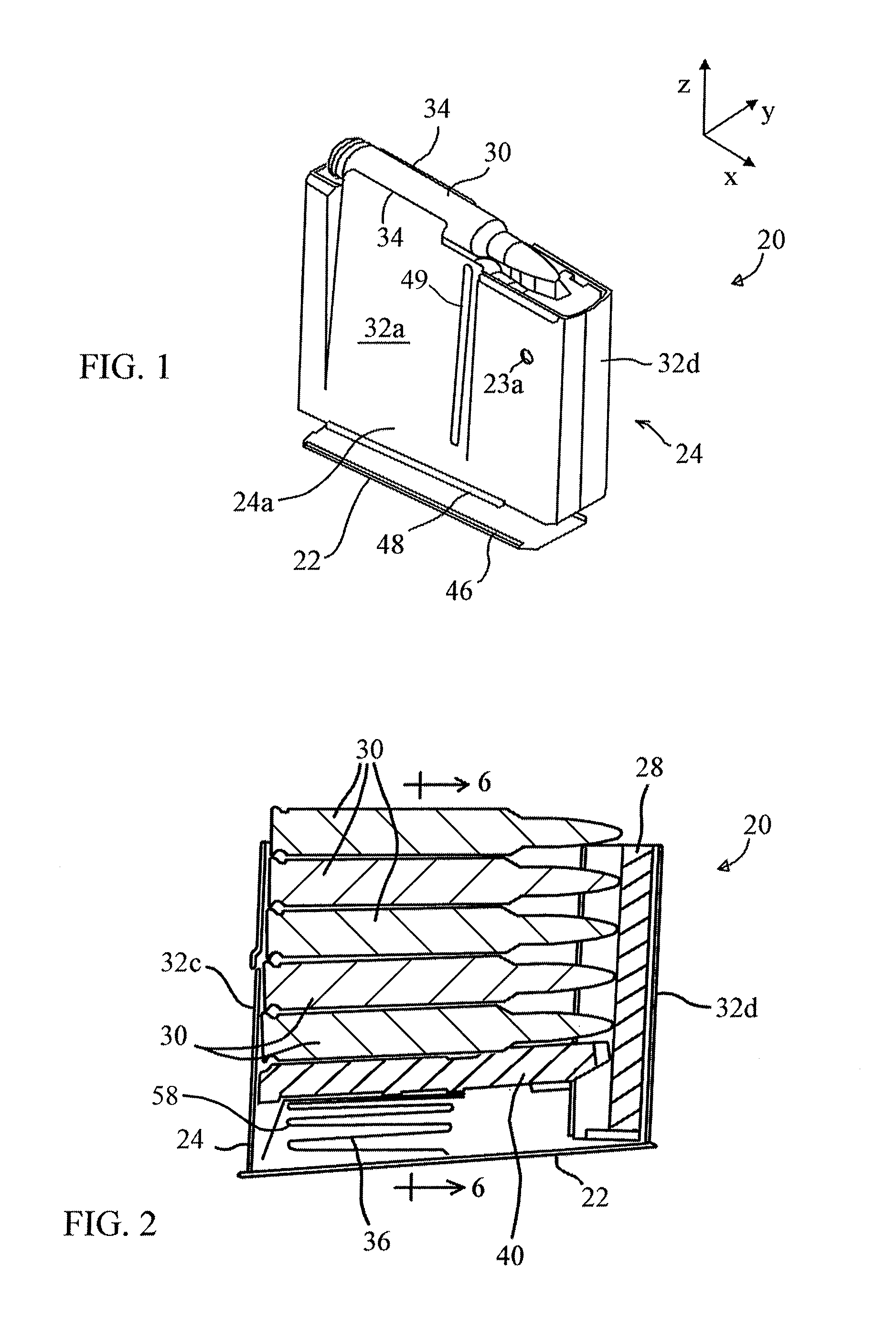
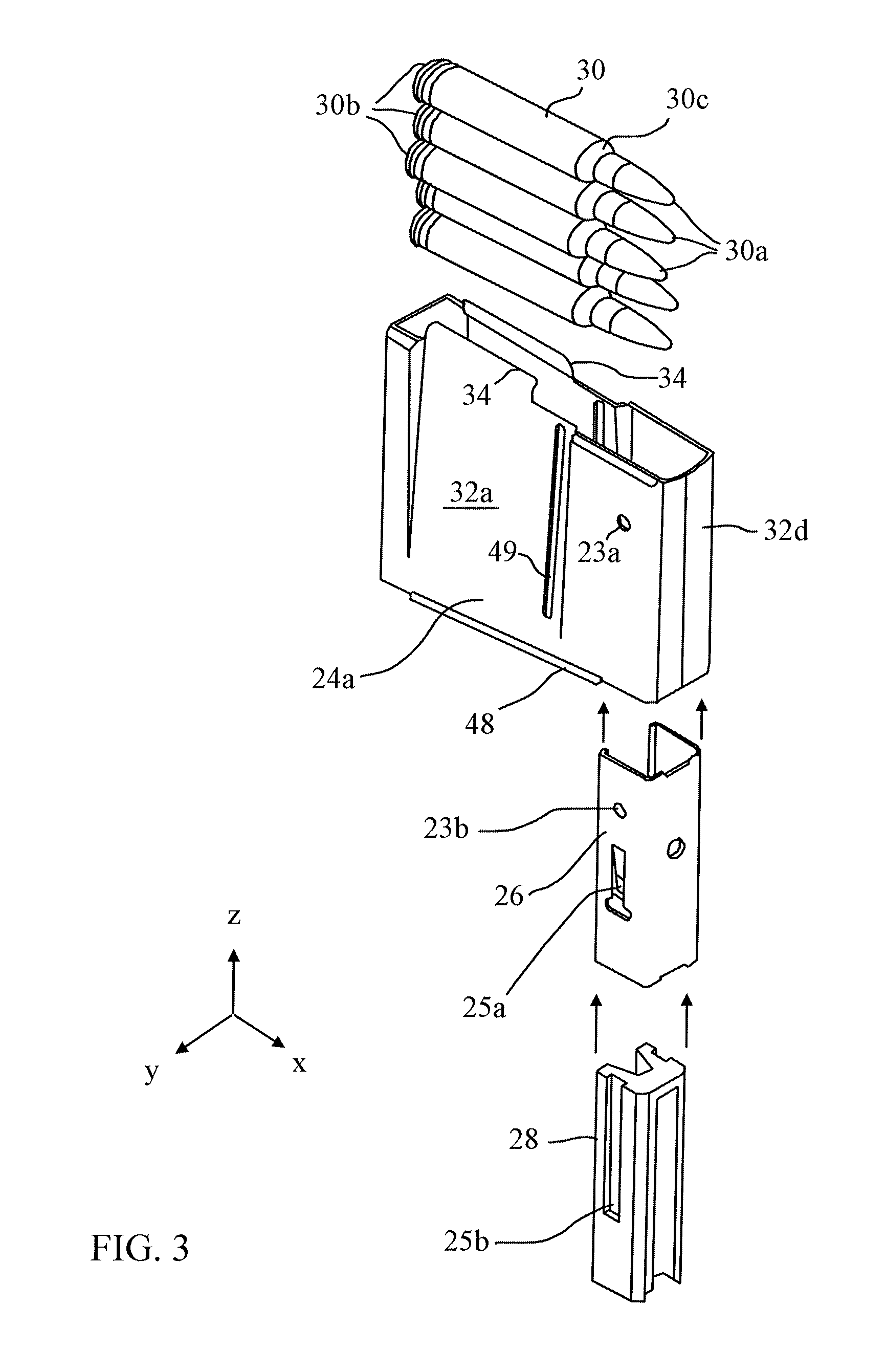
[0036]The magazine of the present invention may be used for rifle length cartridges, but may also be employed with any type of cartridge for automatic or semi-automatic firearms. Magazine 20 comprises housing 24 having generally planar opposing side walls 24a, 24b and rear wall 32c and front wall 32d joining the side walls. Housing 24 may be made of any suitable material metal or polymer, with an example of the former being carbonitrided case hardened 1010 steel of about 0.040 in (1 mm) thickness. Housing 24 may be integrally formed from sheet metal and folded as shown so that the sheet ends contact each other at a seam extending upward midway along the front wall 32d. A floor plate 22 encloses the lower end of housing 24 to define, along with the side walls and front and back walls, an interior space suf...


PUM


Abstract

A firearms magazine has compound tapered side walls and feed lips having substantially parallel end portions for maintaining contact with the cartridge as it is loaded. Removable inserts reduce the interior length and width to hold cartridges of different sizes. One insert has a channel along its height to protect the cartridge noses, and is held by a reinforcing member. A movable cartridge follower feeds the cartridges out of the magazine and has a pair of projections extending along its length for contacting and centering the last cartridge and a projection at one end slideable in the channel of the insert. The follower has one or more downwardly extending members to contact the floor or walls to maintain position of the follower with respect thereto. Projections extending inward from the side walls contact shoulders of the firearms cartridges in sliding relationship as they are fed out of the magazine.

Description

BACKGROUND OF THE INVENTION[0001]1. Field of the Invention[0002]This invention relates to a magazine for feeding cartridges into the chamber of a firearm, and more specifically relates to a firearms magazine for rifle length cartridges and its constitution of specific attributes that enhance more accurate feeding and projectile tip protection.[0003]2. Description of Related Art[0004]Firearms Magazines have been developed for their intended caliber and cartridge length to be held in a specific arrangement and presented to the firearm chamber through various firearm receiver actions. In general the prior art has used basic design guidelines for firearm magazines without specific regards and attributes for determined needs of the operator or shooter. The prior art has not effectively protected the tip of the cartridge projectile from dents or flattening of the apex of the tip, resulting in erratic bullet flight and decreased accuracy. Also, the prior art has not consistently provided e...

Claims


Application Information

Patent Timeline
IPC IPC(8): F41A9/65
CPCF41A9/71
Inventor BATTAGLIA, VINCENT P.
Owner BATTAGLIA VINCENT P
Why Eureka
Try Eureka