Compact lighting system and display device

Inactive Publication Date: 2007-09-11
PHILIPS LUMILEDS LIGHTING CO LLC
View PDF5 Cites 5 Cited by
  • Summary
  • Abstract
  • Description
  • Claims
  • Application Information

AI Technical Summary

Benefits of technology

[0013]By increasing the area of the light input structure, the efficiency with which light originating from the light source is coupled into the light-emitting panel may be increased. A light source based on a light-emitting diode normally comprises a light-emitting part (a chip) covered by a translucent lens-shaped cover. The dimensions of this lens-shaped cover as well as the shape of the light input structure largely determine how (efficiently) light is transferred from the light source to the light-emitting panel.
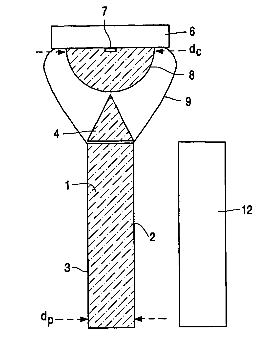
[0015]The tapered shape of the light input structure which gradually narrows in the direction of the light source according to the invention enables the light from the light source to be coupled into the light-emitting panel with a relatively high efficiency. Without being obliged to give any theoretical explanation, there exists an inverse relationship between the thickness of the light-emitting panel and the efficiency with which light from the light source is coupled into the light-emitting panel. Due to the relatively large effective surface of the light input structure, the dimensions of the light-emitting panel can be reduced without the relatively high efficiency with which the light is coupled into the light-emitting panel being adversely affected. A compact lighting system is obtained through the measure according to the invention.
[0020]Preferably, the light-guidance means are elliptically shaped. Elliptically shaped mirrors efficiently guide the light originating from the light source towards the light input structure. In an alternative embodiment the light-guidance means (9) are faceted. Faceting renders it possible to direct the light in specific directions during reflection.
[0021]The light source used may be formed by one or more light-emitting diodes (LEDs) and / or by LEDs of different colors which are combined with one another. Colors may be mixed in a desired manner through a suitable use of LEDs, for example for generating white light of a desired color temperature. Preferably, the light source comprises three light-emitting diodes. The LEDs preferably comprise combinations of red, green, and blue LEDs known per se, or, for example, combinations of red, green, blue, and amber LEDs. LEDs with three light emission wavelengths may also be realized by means of two LEDs with different light emission wavelengths, wherein the LEDs of one of the types are (partly) provided with a phosphor, such that the light emission of the LED is converted by the phosphor into light of a third, desired light emission wavelength. A combination, known per se, of the red, green, and blue LEDs renders it possible to realize color changes independently of the status of the display device. The use of LEDs has the further advantage that dynamic lighting possibilities are obtained. For this purpose, a sensor present at one of the edge surfaces measures the optical properties of the light emitted by the light source during operation.
[0022]The quantity of light emitted by the LEDs is adjusted in that the luminous fluxes of the light-emitting diodes are varied. This control of the luminous flux usually takes place in an energy-efficient manner. Thus the LEDs can be dimmed without an appreciable loss of efficacy. Preferably, the intensity of the light emitted by the light-emitting diodes is variable in response to the illumination level of a picture to be displayed by the display device or in response to the level of the ambient light. Preferably, the color point of a picture displayed by the display device is determined by the lighting system. An (improved) dynamic range (for example contrast) of the picture to be displayed by the display device is achieved thereby.
[0023]Preferably, each of the light-emitting diodes has a luminous flux of at least 10 lm. LEDs with such a high output are also referred to as LED power packages. The use of these high-efficiency, high-output LEDs has the specific advantage that the number of LEDs required for a desired, comparatively high light output can be comparatively small. This benefits the compact construction and the efficiency of the lighting system to be manufactured. Further advantages of the use of LEDs are a comparatively very long service life, the comparatively low energy consumption, and the low maintenance costs for a lighting system with LEDs.

Problems solved by technology

A lighting system of the above type occupies too much space.

Method used


Image

  • Compact lighting system and display device
  • Compact lighting system and display device

Examples


Embodiment Construction

[0028]FIG. 1 is a cross-sectional view of a display device comprising an embodiment of the lighting system according to the invention. The lighting system comprises a light-emitting panel 1 of a light-transmitting material. The panel 1 is manufactured, for example, from a synthetic resin, from acryl, from polycarbonate, from pmma, for example Perspex, or from glass. Light is transported through the light-emitting panel 1 during operation, utilizing total internal reflection (TIR). The light-emitting panel has a front wall 2 and a rear wall 3 opposite thereto. In FIG. 1 at least one light source 6 is provided comprising a light-emitting diode 7 with a translucent lens-shaped cover 8. The lighting system comprises at least one light input structure 4 for coupling light from the light source 6 into the light-emitting panel 1. During operation, light originating from the light source 6 is incident on the light input structure 4 and distributes itself in the light-emitting panel 1. Accor...


PUM


Abstract

A compact backlight system for illuminating a display device has a front wall and a rear wall situated opposite thereto. At least one light source comprising a light-emitting diode is provided with a translucent lens-shaped cover. The system has at least one light input structure for coupling light from the light source into the light-emitting panel. During operation, light originating from the light source is incident on the light input structure and distributes itself in the light-emitting panel. According to the invention the light input structure is conically or frustoconically shaped towards the light source. The thickness dp of the light-emitting panel is smaller than the diameter dc of the translucent lens-shaped cover of the light source. Preferably, the light input structure is of prismatic or pyramidal shape.

Description

BACKGROUND[0001]1. Field of Invention[0002]The invention relates to a lighting system provided with a light-emitting panel.[0003]The invention also relates to a display device provided with said lighting system.[0004]2. Description of Related Art[0005]Edge lighting systems are used inter alia as backlighting systems in (picture) display devices, for example for TV sets and monitors. Such lighting systems are particularly suitable for use as backlights for non-emissive displays such as liquid crystal display devices, also referred to as LCD panels, which are used in (portable) computers or (cordless) telephones.[0006]Said display devices usually comprise a substrate provided with a regular pattern of pixels which are each controlled by at least one electrode. The display device utilizes a control circuit for achieving a picture or a datagraphical display in a relevant field of a (picture) screen of the (picture) display device. The light originating from the backlight in an LCD devic...

Claims


Application Information

Patent Timeline
IPC IPC(8): F21V7/04G02B6/00F21V5/04F21V8/00F21Y101/02G02B6/42G02F1/13357
CPCG02B6/003G02B6/4298G02B6/0016Y10S385/901G02B6/4214G02B6/4203G02B6/00G02B27/00G02B6/0001G02F1/1335
Inventor KEUPER, MATTHIJS HENDRIK
Owner PHILIPS LUMILEDS LIGHTING CO LLC
Why Eureka
Try Eureka