
Combustible ice drilling, mining and gasification separation integrated mining device and combustible ice drilling, mining and gasification separation integrated mining method

A technology for gasification separation and ice drilling, which is applied in drilling equipment and methods, coal gasification, and production of fluids, etc., can solve problems such as affecting the progress of the operation, increasing the load of the sea surface separator, and large energy, so as to improve the operation efficiency and shorten the The effect of operation cycle and operation risk reduction

Inactive Publication Date: 2016-06-15
SOUTHWEST PETROLEUM UNIV
View PDF8 Cites 12 Cited by
  • Summary
  • Abstract
  • Description
  • Claims
  • Application Information

AI Technical Summary

Problems solved by technology

However, when the seabed tunneling vehicle or crusher breaks the combustible ice, it is easy to cause the stratum to collapse, causing the tunneling vehicle or crusher to crash. The cost of salvage and maintenance is high, and it also seriously affects the progress of the operation.
In addition, when the lift pump sucks seawater to lift, the seawater carries combustible ice and formation sand particles to lift together, and is separated at the sea surface, which consumes a lot of energy and increases the load of the sea surface separator

Method used


Image

  • Combustible ice drilling, mining and gasification separation integrated mining device and combustible ice drilling, mining and gasification separation integrated mining method
  • Combustible ice drilling, mining and gasification separation integrated mining device and combustible ice drilling, mining and gasification separation integrated mining method
  • Combustible ice drilling, mining and gasification separation integrated mining device and combustible ice drilling, mining and gasification separation integrated mining method

Examples


Embodiment

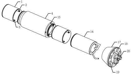
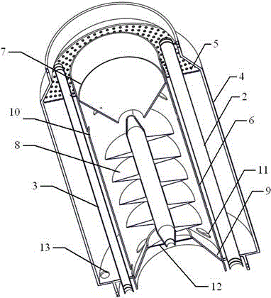
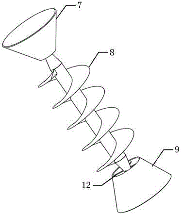
[0034] First assemble the device of the present invention, first connect the suction short and the bottom drill bit through threads, then determine the length of the drill tube 1 between the suction short and the separation short according to actual needs, and connect the drill tube 1 to the suction short. Through screw connection, the drill tubes 1 are assembled one by one, and the drill tube 1 and the separation short are also connected through screw threads. Finally, continue to connect the upper drill pipe 1 at the upper part of the separation short circuit. During the installation process of the suction short circuit, the drill barrel 1, and the separation short circuit, the water injection pipe 3 and the hot water pipe 2 at the corresponding positions are also connected and assembled one by one. After the installation of the device is completed, place it in the place where the combustible ice deposit is to be mined.

[0035] When drilling, start the roller cone bit 20, ...


PUM


Abstract

The invention relates to a combustible ice drilling, mining and gasification separation integrated mining device and a combustible ice drilling, mining and gasification separation integrated mining method. The combustible ice drilling, mining and gasification separation integrated mining device is formed by a separation short joint, a suction short joint, a bottom drill bit, a drill cylinder, a hot water pipe and a water injection pipe, wherein the suction short joint is connected with the bottom drill bit; the drill cylinder is connected between the suction short joint and the separation short joint; the length of the drill cylinder is determined according to needs; the water injection pipe and the hot water pipe penetrate through the drill cylinder and the two short joints. According to the combustible ice drilling, mining and gasification separation integrated mining device disclosed by the invention, integration of drilling, mining and gasification separation of combustible ice can be realized through the cooperation of five links of cutting and crushing of the bottom drill bit, water injection and fluidization of the water injection pipe, hot water injection, heat transfer and energy transfer of the hot water pipe, suction of the suction short joint and separation of the separation short joint; a drilling technology, a mining technology and a separation technology are combined, a process is simplified, the period is shortened, the efficiency is increased, and the cost and the risk are reduced.

Description

technical field [0001] The invention belongs to the technical field of seabed combustible ice mining, and in particular relates to an integrated mining device and method for combustible ice drilling and mining, gasification and separation. technical background [0002] Combustible ice is a cage-shaped crystal formed by methane-based natural gas and water under low-temperature and high-pressure environments. It has high density, high calorific value, and flammable properties. It is mainly stored in the seabed and land permafrost at high latitudes. , about 95% are stored in the deep water area of ​​0-1100m below the seabed with a water depth greater than 300m, and the shallow fine-grained fracture type and dispersed type are the main types. As a green and clean energy source, combustible ice has attracted worldwide attention since its discovery. It only exists under certain temperature and pressure conditions. Once the conditions are broken, it will cause gasification and deco...

Claims


Application Information

Patent Timeline
IPC IPC(8): E21B7/00E21B43/295E21B43/24E21B43/38
CPCE21B7/008E21B43/24E21B43/295E21B43/38
Inventor 朱红钧唐丽爽
Owner SOUTHWEST PETROLEUM UNIV
Learn More