
Quantitative box for oil drain ring

The technology of a quantitative box and an oil drain ring is applied in the field of devices for quantitative biosurfactant substances, which can solve the problems of inaccurate observation, inability to observe, and great influence, and achieve the effect of convenient use.

Active Publication Date: 2018-08-28
OCEAN UNIV OF CHINA
View PDF6 Cites 0 Cited by
  • Summary
  • Abstract
  • Description
  • Claims
  • Application Information

AI Technical Summary

Problems solved by technology

[0004] The traditional oil discharge ring method mainly has the following problems: 1. The culture dish is open and is greatly affected by the surrounding environment
; 3. The stability time of the oil discharge ring is short, and the observation is often inaccurate or even impossible to observe
Immediately after adding the biosurfactant solution, it is observed that the formed oil drainage circle is not stable, and it is difficult to accurately reflect the actual content of biosurfactant by the size of the oil drainage circle
In addition, the stable time of the formed oil discharge ring is very short, and the oil discharge ring is easy to break the oil film, which makes it impossible to observe the experimental results
[0005] In addition, we have to pay attention to the fact that the biosurfactant in the prior art is often a mixture of two or more biosurfactants or a mixture of multiple surfactants, and the traditional method cannot realize the determination of its total content. Therefore, it cannot provide its surface active ability

Method used


Image

  • Quantitative box for oil drain ring
  • Quantitative box for oil drain ring

Examples


Embodiment Construction

[0022] The present invention will be further described below in conjunction with accompanying drawing:

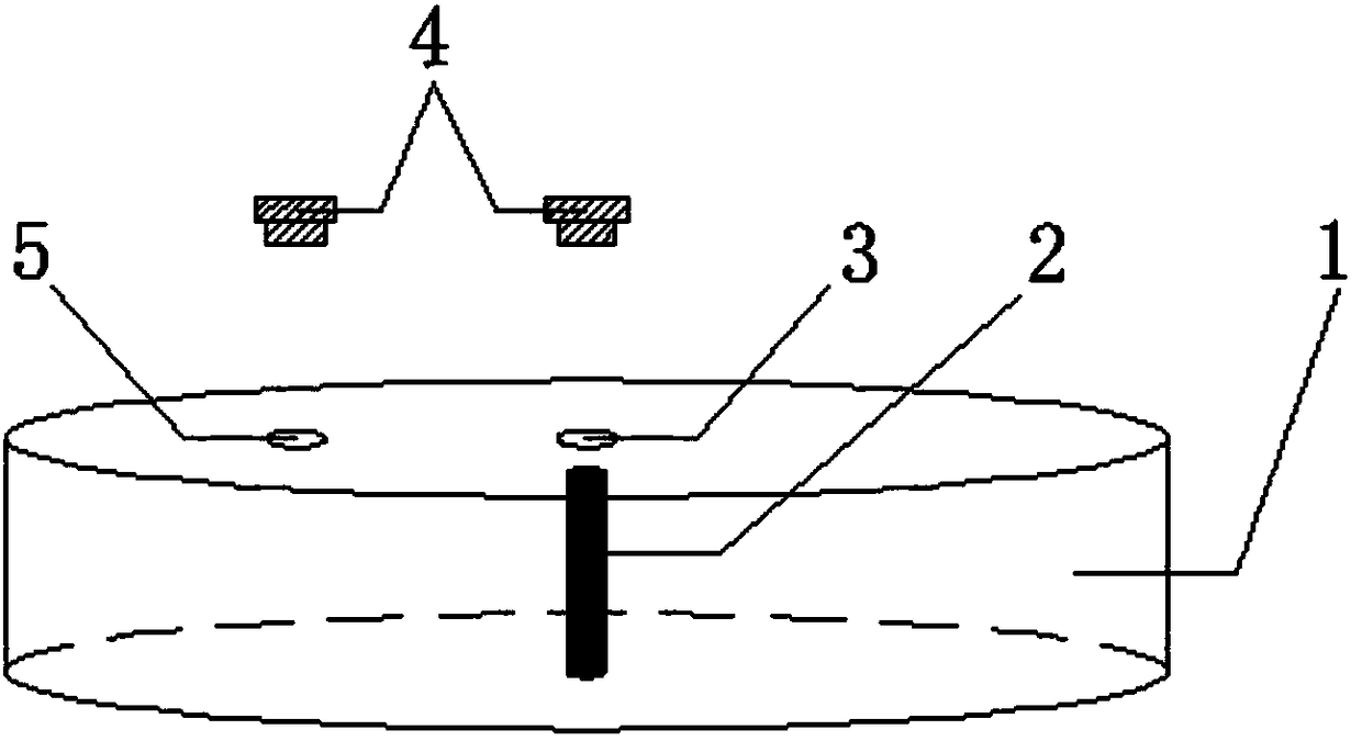
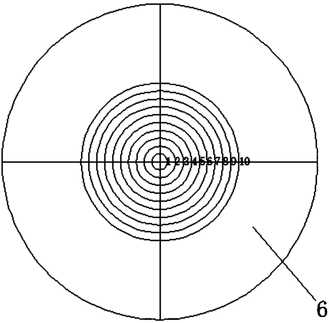
[0023] Such as figure 1 with figure 2 Shown: the present invention comprises quantitative box 1, sample injection column 2, sealing plug 4 and quantitative dial 6, described quantitative box 1 is a circular transparent box body, and described sample injection column 2 is a solid glass column, and described sample injection The lower end of the column 2 is fixed in the middle of the bottom of the quantitative box 1, the upper end of the injection column 2 has a gap of 3 cm from the cover of the quantitative box 1, and the middle part of the cover of the quantitative box 1 is provided with an injector. Sample hole 3, the sample injection hole 3 is located above the sample injection column 2, the lid side of the quantitative box 1 is provided with a material injection hole 5, the sealing plug 4 is two, one of the sealing plugs The plug 4 is connected to the injection hole 3...


PUM

PropertyMeasurementUnit
porosityaaaaaaaaaa

Abstract

The invention discloses an oil spreading quantifying box, comprising a quantifying box, a sample injection column, sealing plugs and a quantitative dial, wherein the quantifying box is a circular transparent box body; the sample injection column is a solid glass column; the lower end of the sample injection column is fixed in the middle of the bottom in the quantifying box, and a 3cm of gap is reserved between the upper end of the sample injection column and a cover body of the quantifying box; a sample injection hole is formed in the middle of the cover body of the quantifying box and is positioned above the sample injection column; a material injection hole is formed in one side of the cover body of the quantifying box; one of the two sealing plugs is connected with the sample injection hole, and the other sealing plug is connected with the material injection hole; the quantitative dial is made of transparent material; the quantitative dial is provided with ten equally divided rings which are marked with numerical symbols. Compared with the prior art, the oil spreading quantifying box is capable of conveniently, rapidly, accurately and stably measuring the content of a biological surfactant; after the oil spreading quantifying box is used, the quantitation standards for different types of biological surfactants or one biological surfactant in different environments can be established; the oil spreading quantifying box is convenient to use and has popularization and application values.

Description

technical field [0001] The invention relates to a device for quantifying biosurfactant substances, in particular to an oil discharge circle quantitative box. Background technique [0002] Biosurfactants are metabolites with certain surface activity secreted by microorganisms or plants during their metabolic process when they are cultured under certain conditions. The molecular structure of biosurfactants mainly consists of two parts: one part is an oleophobic and hydrophilic polar group, and the other part is a nonpolar group composed of hydrophobic and lipophilic hydrocarbon chains. The types of biosurfactants include glycolipids synthesized by Pseudomonas, lipopeptides synthesized by Bacillus, phospholipids synthesized by other microorganisms, lipopolysaccharides or neutral lipid derivatives, etc. Biosurfactants have the characteristics of good solubilization, significantly reducing surface tension, and stabilizing emulsions. In addition, it also has the advantages of be...

Claims


Application Information

Patent Timeline
Patent Type & Authority Patents(China)
IPC IPC(8): G01N13/02
CPCG01N13/02G01N2013/0275
Inventor 包木太方超包凯文李浩帅
Owner OCEAN UNIV OF CHINA
Learn More