Stereo camera supporting apparatus, stereo camera supporting method, calibration detection apparatus, calibration correction apparatus, and stereo camera system
A technology of stereo cameras, supporting devices, applied in the direction of measuring devices, using optical devices, measuring distances, etc.
- Summary
- Abstract
- Description
- Claims
- Application Information
AI Technical Summary
Problems solved by technology
Method used
Image
Examples
no. 1 Embodiment approach
[0133] Figure 6 It is a diagram showing a configuration example of the stereo camera coupling device 56 of the stereo camera support device 50 according to the first embodiment of the present invention.
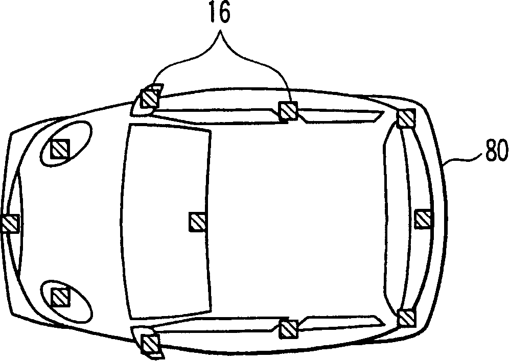
[0134] The stereo camera coupling device 56 is a coupling member for mounting the stereo camera 16 on the vehicle 80 and can control the stereo camera 16 to freely change to a desired position and posture. Both ends of the stereo camera coupling device 56 are provided with a supporting member 84 fixed to an appropriate part of the vehicle body for coupling with the vehicle body, and a supported component 86 for coupling with the stereo camera 16 .
[0135] In addition, there is provided a mechanism for allowing the stereo camera 16 integrated in the vehicle body to be freely oriented within a predetermined range. That is, this mechanism is an attitude control mechanism and includes a pan rotation motor 88a, a pitch rotation motor 88b, and a roll rotation motor 88c that can ...
no. 2 Embodiment approach
[0166] Next, a stereo camera support device 50 according to a second embodiment of the present invention will be described.
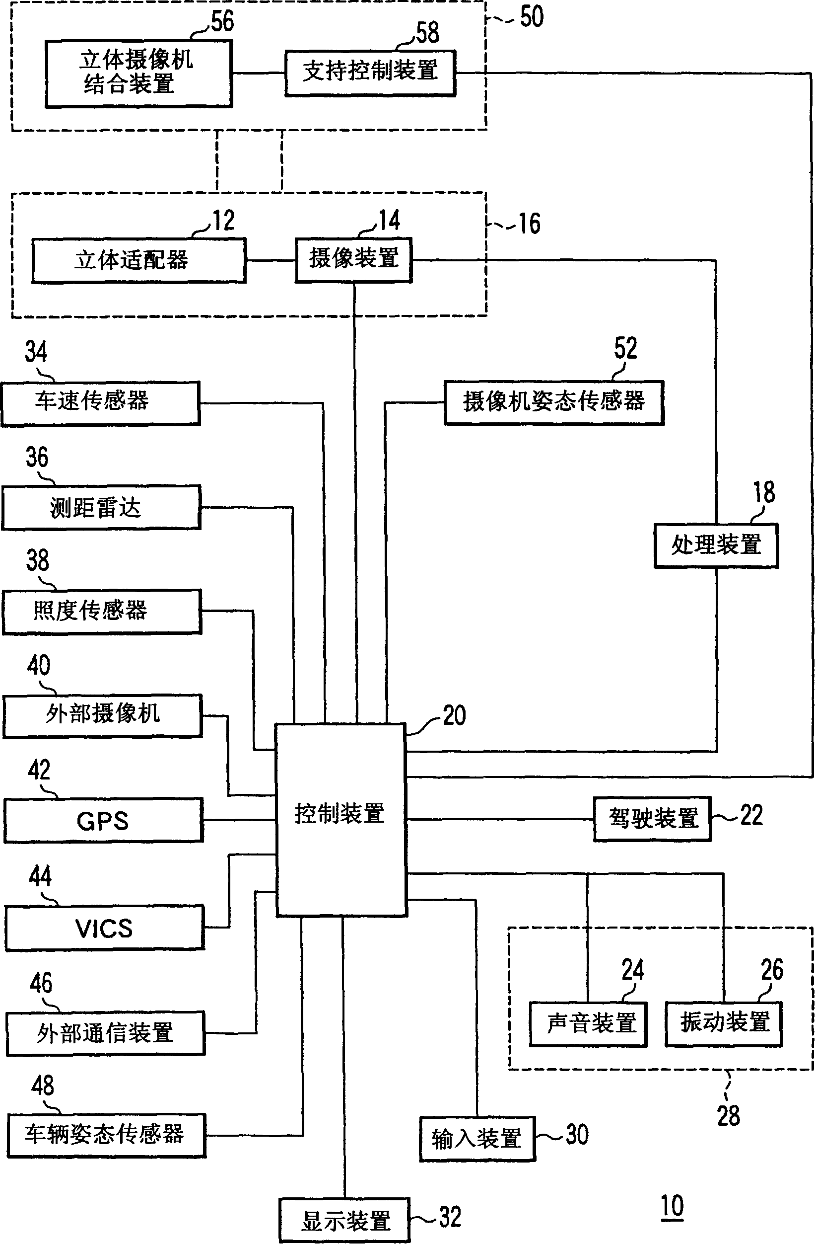
[0167] The stereo camera support device 50 of the second embodiment is included in the same manner as the stereo camera support device 50 of the first embodiment described above. figure 1 shown in the stereo camera system to be applied. In addition, the configuration of the stereo camera combination device 56 of the second embodiment is the same as Figure 6 The configuration of the stereo camera combination device 56 of the first embodiment shown is the same. Therefore, the same reference numerals are assigned to the same parts as in the first embodiment, and detailed description thereof will be omitted.
[0168] Next, the operation of the stereo camera support device 50 according to the second embodiment of the present invention will be described. In the present embodiment, the stereo camera support device 50 corrects changes in the field of view c...
no. 3 Embodiment approach
[0183] Next, a stereo camera support device 50 according to a third embodiment of the present invention will be described.
[0184] The stereo camera support device 50 of the third embodiment is included in the same manner as the stereo camera support device 50 of the first embodiment described above. figure 1 shown in the stereo camera system to be applied. In addition, the configuration of the stereo camera combination device 56 of the third embodiment is the same as Figure 6 The configuration of the stereo camera combination device 56 of the first embodiment shown is the same. Therefore, the same reference numerals are assigned to the same parts as in the first embodiment, and detailed description thereof will be omitted.
[0185] Next, the operation of the stereo camera support device 50 according to the third embodiment of the present invention will be described. In the present embodiment, the stereo camera support device 50 corrects a change in the field of view caus...
PUM
 Abstract
Description
Claims
Application Information
 - R&D
- Intellectual Property
- Life Sciences
- Materials
- Tech Scout
- Unparalleled Data Quality
- Higher Quality Content
- 60% Fewer Hallucinations
Browse by: Latest US Patents, China's latest patents, Technical Efficacy Thesaurus, Application Domain, Technology Topic, Popular Technical Reports.
© 2025 PatSnap. All rights reserved.Legal|Privacy policy|Modern Slavery Act Transparency Statement|Sitemap|About US| Contact US: help@patsnap.com


