
Method for detecting glass by disc wheel rotary table rack image pick-up step press plate

A pressure plate detection, rack technology, applied in the direction of measuring devices, instruments, scientific instruments, etc., can solve the problems of long time consumption, low efficiency of tempered glass installation, operator injury, etc., achieve high overall structural strength, improve labor intensity, time consuming effect

Inactive Publication Date: 2016-06-08
WENZHOU ECONOMIC TECH DEV ZONE HAIZHIJIE ELECTROMECHANICAL PROD DESIGN STUDIO
View PDF4 Cites 8 Cited by
  • Summary
  • Abstract
  • Description
  • Claims
  • Application Information

AI Technical Summary

Problems solved by technology

This method is not only inconvenient to operate, it takes a long time, and the tape is a disposable product, which is easy to cause waste and pollution, and the tape residue on the test bench must be removed after each test to remove the broken glass, otherwise , the remaining glass fragments will affect the next experimental test operation
At the same time, the adhesive tape is also likely to be broken by the force of the tempered glass explosion, causing the operator to be injured. Therefore, it is very necessary to improve the tempered glass fragment test device
[0005] Chinese patent application number: 2009203050079, tempered glass falling ball test bench, in order to solve the problem of glass fragments splashing everywhere when tempered glass is used for experiments, the method of supporting the frame box is adopted. Although the glass fragments can be collected effectively, it is inconvenient to read the glass fragments. , and the installation efficiency of continuous multi-piece tempered glass is low

Method used


Image

  • Method for detecting glass by disc wheel rotary table rack image pick-up step press plate
  • Method for detecting glass by disc wheel rotary table rack image pick-up step press plate
  • Method for detecting glass by disc wheel rotary table rack image pick-up step press plate

Examples


Embodiment Construction

[0072] Describe the present invention in detail below in conjunction with accompanying drawing and specific embodiment:

[0073] figure 1 , figure 2 , image 3 , Figure 4 , Figure 5 , Figure 6 , Figure 7 , Figure 14 , Figure 15 , Figure 16 , Figure 17 , Figure 18 , Figure 20 and Figure 21 In this method, the method of detecting glass by using the pan-lun turntable rack camera ladder pressure plate, the overall frame includes the support side plate 200, the rear shear plate 176, the bottom narrow plate 175 and four circular columns 566, and the support side plates 200 on both sides The two circular columns 566 are respectively fixed, the upper ends of the four circular columns 566 are fixed with column ends 604, and the four column ends 604 are respectively fixed with two horizontal horizontal bars 602 and two longitudinal horizontal bars 603 ;

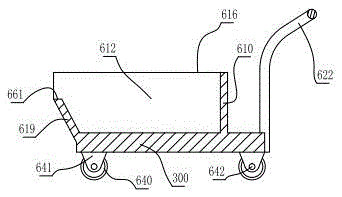
[0074] The upper planes of the supporting side plates 200 on both sides are respectively fixed with a platf...


PUM


Abstract

The invention relates to a toughened glass test inspection method, in particular to a method for detecting glass by a disc wheel rotary table rack image pick-up step press plate. Through improvement, the toughened glass fragment test comprises the following steps that 1, a disc wheel crank handle is anticlockwise rotated, and a test table plate is in a horizontal state; 2, a press plate fixing plate, a press plate right side, a press plate opposite side and a press plate left side with the same structures are put on the test table plate to surround an ambient surrounding space; 3, the toughened glass to be tested is put on the test table plate in the ambient surrounding space, so that a rubber press sheet on each press plate is attached to the outer edges of the four sides of the toughened glass to be tested; 4, when the conical tip of an impact hammer is downward moved to the lowest position, the toughened glass is crushed through impacting; 5, an image-pickup motor is started; image-pickup shooting is performed; a fragment image is transmitted to a computer processing center; whether the crushed toughened glass is qualified or not is judged according to national standard requirements; the fragment state test of the toughened glass is completed.

Description

technical field [0001] The invention relates to a test and inspection method for tempered glass, in particular to a method for inspecting glass by using a test and inspection method equipped with an industrial camera instead of manual operation and using a pan-lun turntable rack camera to take pictures of a stepped pressure plate. Background technique [0002] Fragmentation state test is one of the contents of mechanical performance inspection, the purpose of the test is to evaluate the possibility of injury caused by fragments when the safety glass is broken. my country is the same as Japan and the European Community in terms of safety glass testing methods and results. In the process of fragment state inspection, it is necessary to record the number, shape and size of fragments within a 50mm×50mm square that meet the requirements after the sample glass is broken. Due to the irregular shape and large number of fragments produced after glass breaking, manual methods are cu...

Claims


Application Information

Patent Timeline
IPC IPC(8): G01N3/317G01N3/02G01N3/06
CPCG01N3/02G01N3/068G01N3/317
Inventor 张志雄
Owner WENZHOU ECONOMIC TECH DEV ZONE HAIZHIJIE ELECTROMECHANICAL PROD DESIGN STUDIO
Learn More