
Cylindrical material filling mechanism

A filling mechanism and cylindrical technology, which is applied in the field of workpiece conveying and filling mechanism to achieve the effect of reducing failure rate, improving storage mode and ensuring stability

Active Publication Date: 2016-06-08
ACADEMY OF ARMORED FORCES ENG PLA
View PDF6 Cites 3 Cited by
  • Summary
  • Abstract
  • Description
  • Claims
  • Application Information

AI Technical Summary

Problems solved by technology

However, at present, the automatic feeding mechanism of the stamping production line can only realize the automatic feeding process of small-volume materials. How to automatically fill the large-volume cylindrical materials is an urgent problem to be solved to realize the automation of the stamping production line.

Method used

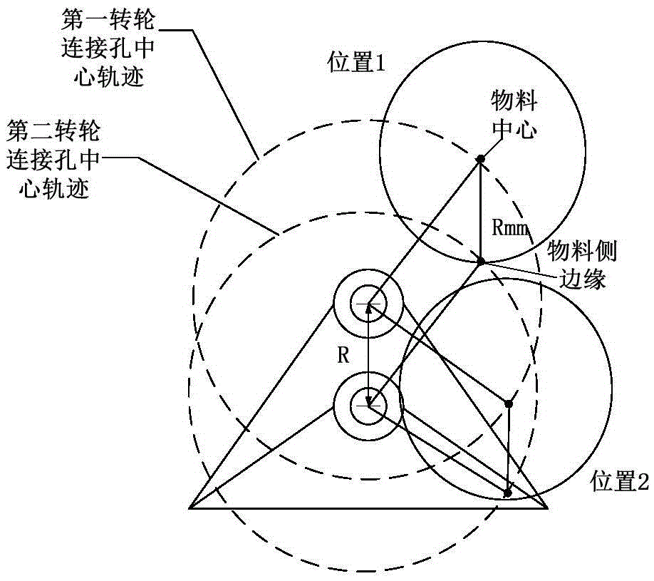
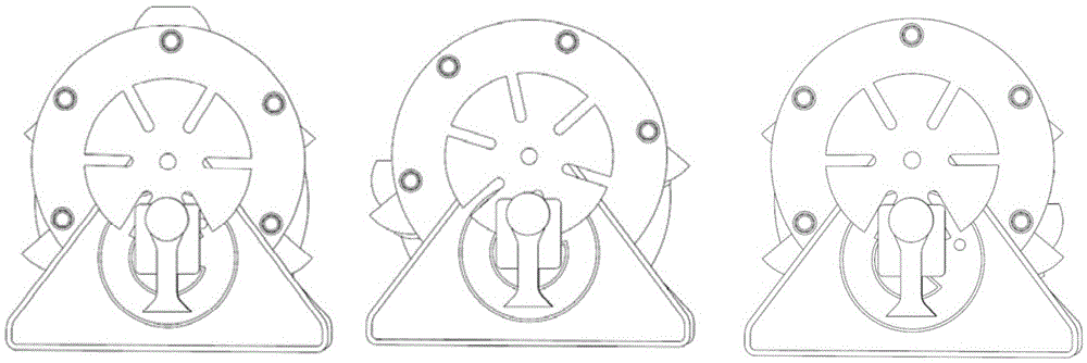

Image

  • Cylindrical material filling mechanism
  • Cylindrical material filling mechanism
  • Cylindrical material filling mechanism

Examples


Embodiment Construction

[0013] The following is attached Figure 1-3 The technical solution of the present invention is described in detail.

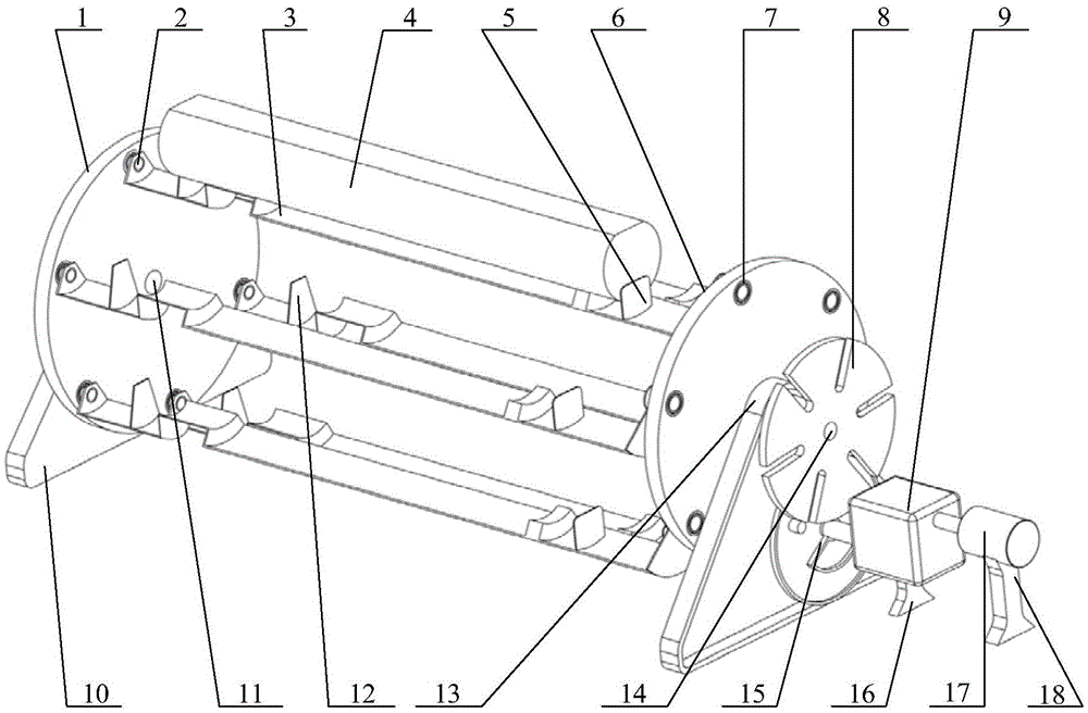
[0014] Such as Figure 1-3 As shown, the present invention provides a cylindrical material loading mechanism, comprising a first runner 1, a material bottom support connecting pin 2, a material bottom support 3, a cylindrical material 4, a material bottom edge baffle 5, a second runner 6. Bearing 7, sheave 8, deceleration device 9, first bracket 10, runner connecting pin 11, cylindrical material front end baffle 12, second bracket 13, sheave connecting pin 14, dial 15, deceleration device support Frame 16, motor 17, motor support frame 18.

[0015] Wherein: the first runner 1 is connected on the first bracket 10 through the runner connecting pin 11, and can rotate around the runner connecting pin 11, and the second runner 6 is connected on the second bracket 13 through the runner connecting pin 11 , and can rotate around the connecting pin 11 of the runner,...


PUM


Abstract

The invention relates to a cylindrical material filling mechanism. The cylindrical material filling mechanism comprises a first turning wheel (1), material bottom support connecting pins (2), material bottom supports (3), material bottom edge baffles (5), a second turning wheel (6), bearings (7), a grooved wheel (8), a speed reducing device (9), a first support (10), turning wheel connecting pins (11), cylindrical material front end baffles (12), a second support (13), a grooved wheel connecting pin (14), a shifting wheel (15), a speed reducing device supporting frame (16), a motor (17) and a motor supporting frame (18). A pure mechanical structure is adopted by the filling mechanism, so that the fault rate is decreased; through a spatial parallelogram mechanism of the filling mechanism, the postures of cylindrical materials are unchanged all the time (facing upwards); and the gravity of the cylindrical materials are borne by the material bottom supports all the time, so that the elasticity storage stability and elasticity supply stability of the filling mechanism are guaranteed.

Description

technical field [0001] The invention relates to a workpiece conveying and filling mechanism, in particular to a cylindrical material filling mechanism. technical background [0002] At present, the existing five hot stamping production lines in China are all high-priced imported foreign production lines (such as Baosteel, Shanghai Cosma, etc.), which are used for the production of core components and cost a lot of money, resulting in high market costs. [0003] For realizing the goal of industrialization, the equipment of the hot stamping forming production line mainly includes 4 parts: high-speed special hydraulic press that meets the requirements of fast mold clamping and pressure maintaining; water-cooled mold with optimal cooling circuit design and meeting the requirements of forming process; ensuring positioning accuracy A special heating furnace with anti-oxidation and controllable rhythm; an automatic transmission system with central controllable joint debugging funct...

Claims


Application Information

Patent Timeline
Patent Type & Authority Applications(China)
IPC IPC(8): B65G29/00
CPCB65G29/00B65G2201/0214
Inventor 徐达李洋罗建华李华钟孟春何凯平焦庆龙李闯罗业范文博
Owner ACADEMY OF ARMORED FORCES ENG PLA
Learn More