
Boss molding process for pipe

A forming process and technology for pipe fittings, applied in the field of boss forming process of pipe fittings, can solve the problems of insufficient welding strength, high production cost, low production efficiency, etc. Effect

Inactive Publication Date: 2016-06-08
FOSHAN GUANGTENG NEW ENERGY CO LTD
View PDF6 Cites 2 Cited by
  • Summary
  • Abstract
  • Description
  • Claims
  • Application Information

AI Technical Summary

Problems solved by technology

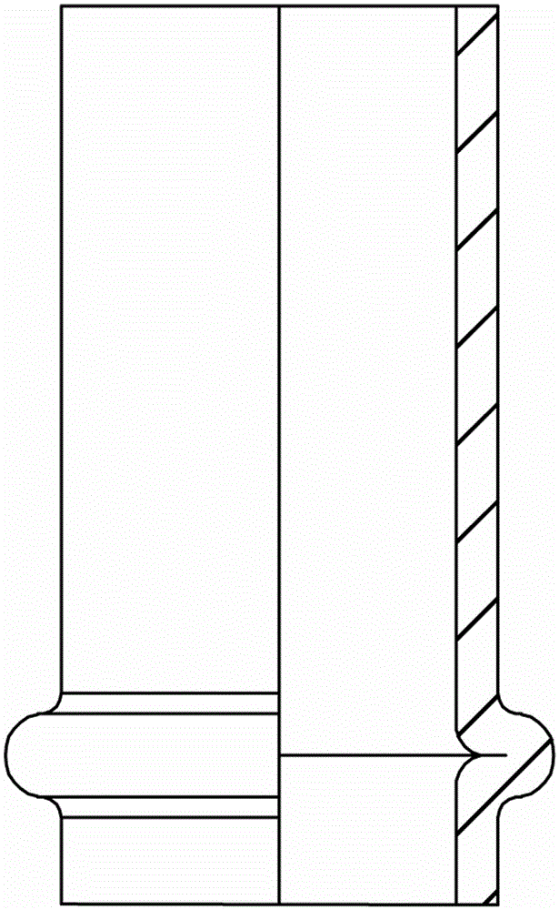
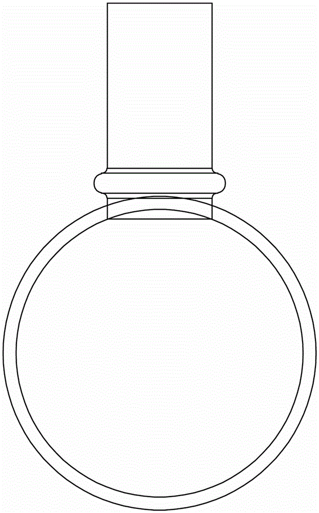
However, if Figure 1 to Figure 2 As shown, the current general bosses are in the shape of a ring. On the same plane, when the small tube is inserted into the large tube for welding, the contact area between the bottom of the boss and the wall of the large tube is very small, and the welding strength is insufficient. , the welding is not firm, and the direction of the small tube is easy to deviate
Insufficient welding strength between the small tube and the large tube is the main reason for the rupture of the welded joint, which is prone to refrigerant leakage and has a great impact on the quality of the machine
Therefore, domestic refrigerant pipe manufacturers have developed a pipe fitting with an arc-shaped boss in response to this problem. The arc-shaped annular boss can not only control the insertion depth of the pipe fitting, but also ensure that the two pipes are firmly welded and not easily displaced during welding. Deformed, but the forming process of the arc-shaped annular boss of the existing pipe fittings is complicated, the processing is time-consuming and laborious, the production cost is high, and the production efficiency is low

Method used


Image

  • Boss molding process for pipe
  • Boss molding process for pipe
  • Boss molding process for pipe

Examples


Embodiment 1

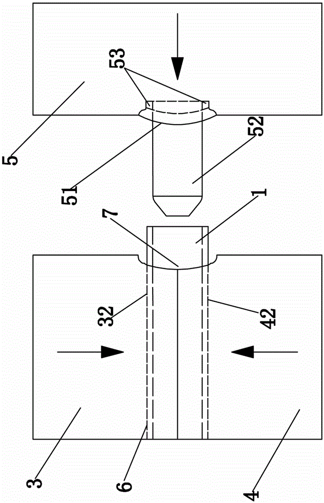
[0029] Embodiment one, such as Figure 3 to Figure 8 As shown, a boss forming device for pipe fittings includes an upper clamp 3, a lower clamp 4 and a stamping die 5, and the upper clamp 3 and the lower clamp 4 are respectively provided with an upper pinch groove 32 and a lower pinch groove 42, The ends of the upper clamping groove 32 and the lower clamping groove 42 are respectively provided with an upper half die 31 and a lower half die 41. After the upper clamp 3 and the lower clamp 4 are combined, the upper clamping groove 32 and the lower clamp 4 are assembled. The lower clamping groove 42 is assembled into a pipe cavity 6, and the lower half die 41 and the upper half die 31 are assembled into a tubular curved surface die 7, and the bottom of the tubular curved surface die 7 is connected with the pipe cavity. 6 connected.

[0030] Described stamping mold 5 is respectively provided with positioning pin 52 and curved surface punch 51 corresponding to tubular cavity 6 and ...


PUM

PropertyMeasurementUnit
lengthaaaaaaaaaa

Abstract

The invention relates to a boss molding process for a pipe. The boss molding process for the pipe comprises the following steps that 1, a material is fetched, the pipe to be machined is put on a lower pipe clamping groove of a lower clamp firstly, and the to-be-machined end of the pipe is kept to extend out of a lower half female die of the lower clamp; 2, the pipe is clamped, then an upper clamp and the lower clamp are started to oppositely move for die assembly, the lower half female die and an upper half female die are spliced into a pipe type curve female die, an upper pipe clamping groove of the upper clamp and the lower pipe clamping groove of the lower clamp are spliced into a pipe type cavity and clamps the pipe tightly, and a pipe orifice of the to-be-machined end of the pipe is kept to be aligned at a positioning pin on a stamping die; 3, stamping is conducted, the stamping die is started, an annular stamping concave cavity between the positioning pin and a curve male die starts to stamp the outer wall of the pipe, and an arc-shaped annular boss is formed on the outer wall of the pipe under the extrusion effect of the pipe type curve female die and the curve male die; and 4, the pipe is taken out. Compared with an existing arc-shaped annular boss molding process, the boss molding process for the pipe is simple, low in production cost and high in production efficiency.

Description

technical field [0001] The invention relates to a welding process for pipe fittings with different diameters, in particular to a boss forming process for pipe fittings. Background technique [0002] In the production process of air conditioners and heat pumps, the most commonly used refrigerant pipelines are purple pipe fittings, and the connection methods between purple pipe fittings are even more varied. One of the more common connection methods between large pipes and small pipes is in large pipes. Drill a hole in the wall, then insert the small tube into the drilled hole, and heat the welded connection. Because the diameter of the drill hole is larger than the diameter of the small tube, it is difficult to uniformly insert the small tube. If the small tube is inserted too deep, it will block the flow of the large tube. If it is inserted too shallow, the welding joint is easy to break. Therefore, in order to control the insertion depth of the small tube A commonly used m...

Claims


Application Information

Patent Timeline
Patent Type & Authority Applications(China)
IPC IPC(8): B21D22/02
CPCB21D22/025
Inventor 冯永坚罗志锋罗增亮
Owner FOSHAN GUANGTENG NEW ENERGY CO LTD
Learn More