
Self-adaptive speed regulating method and system having maximum deceleration

A technology of speed regulation system and speed regulation method, which is applied in the direction of control system, vector control system, control generator, etc., and can solve problems such as crash, low safety performance, overvoltage system, etc.

Inactive Publication Date: 2016-06-01
CSR ZHUZHOU ELECTRIC LOCOMOTIVE RES INST
View PDF4 Cites 0 Cited by
  • Summary
  • Abstract
  • Description
  • Claims
  • Application Information

AI Technical Summary

Problems solved by technology

In actual engineering, some systems cannot install choppers and braking resistors due to various reasons. Therefore, during the deceleration process, if the deceleration is too large, it will cause the intermediate voltage to overvoltage and cause the system to collapse, and the safety performance is low.

Method used


Image

  • Self-adaptive speed regulating method and system having maximum deceleration
  • Self-adaptive speed regulating method and system having maximum deceleration
  • Self-adaptive speed regulating method and system having maximum deceleration

Examples


Embodiment Construction

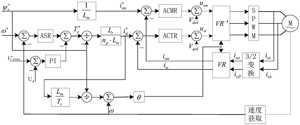
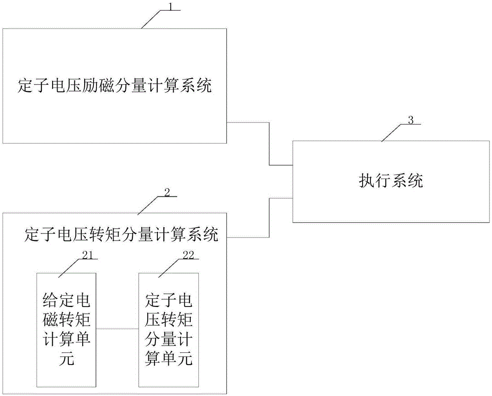
[0035] The core of the present invention is to provide an adaptive speed regulation method with the maximum deceleration, which not only controls the given electromagnetic torque through the rotating speed It also controls the given electromagnetic torque through the closed loop of the intermediate voltage The intermediate voltage will not be overvoltage while the speed regulating system has the maximum deceleration, which improves the speed regulating performance and safety performance of the speed regulating system; another core of the present invention is to provide an adaptive speed regulating system with the maximum deceleration speed system.

[0036] In order to make the purpose, technical solutions and advantages of the embodiments of the present invention clearer, the technical solutions in the embodiments of the present invention will be clearly and completely described below in conjunction with the drawings in the embodiments of the present invention. Obviously, th...


PUM


Abstract

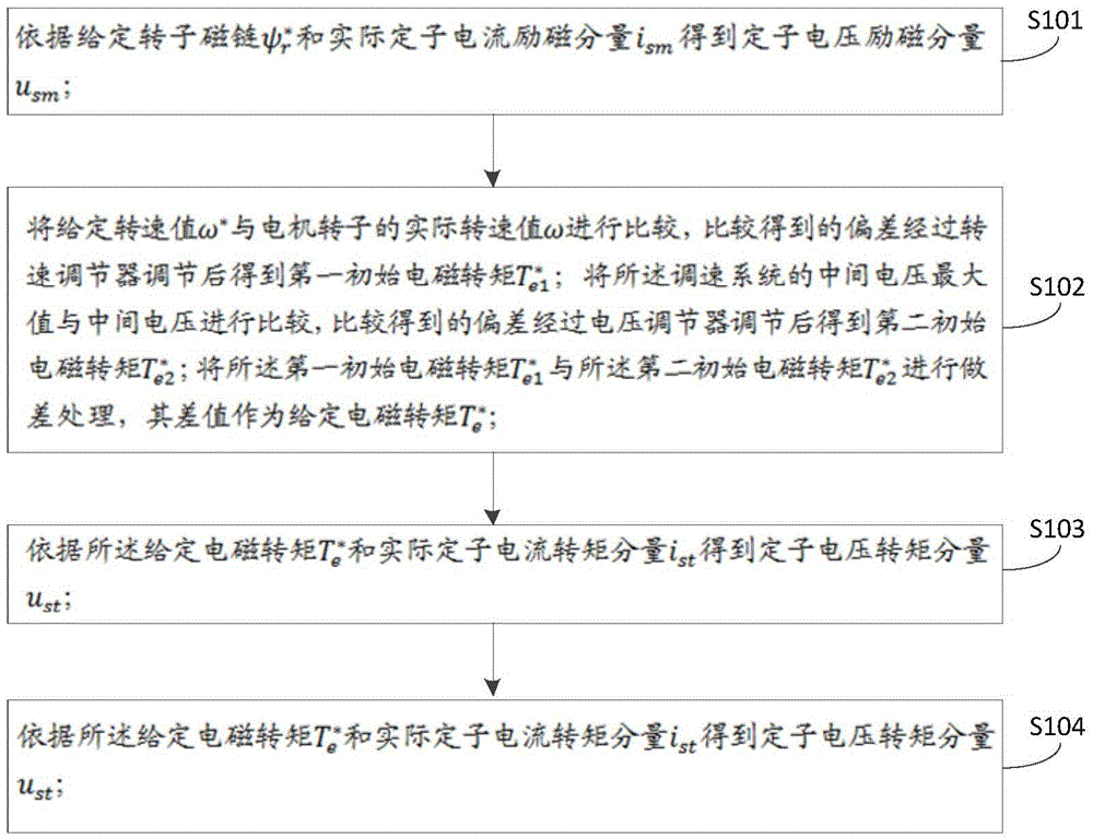
The invention discloses a self-adaptive speed regulating method and system having a maximum deceleration. The method comprises the steps: according to a given rotor magnetic flux linkage Psi<r>* and a real stator current excitation component i<sm>, obtaining a stator voltage excitation component u<sm>; comparing a given rotation speed value omega* and a real rotation speed value omega of a motor rotor, regulating a deviation obtained through the comparison by virtue of a rotation speed regulator to obtain a first initial electromagnetic torque Tau<e1>*, comparing an intermediate voltage maximum value and an intermediate voltage of a speed regulating system, regulating a deviation obtained through the comparison by virtue of a voltage regulator to obtain a second initial electromagnetic torque Tau<e2>*, performing the difference processing on Tau<e1>* and Tau<e2>*, taking the difference value as a given electromagnetic torque Tau<e>*, and obtaining a stator voltage torque component u<st> according to Tau<e>* and the real stator current torque component i<st>; controlling a motor according to the stator voltage excitation component u<sm> and the stator voltage torque component u<st> until the balance is finally achieved, so that the self-adaptive speed regulation of the motor is realized. By adopting the self-adaptive speed regulating method and system, while the speed regulating system has the maximum deceleration, the intermediate voltage is not excessive, and the speed regulating performance and the safety performance of the speed regulating system are improved.

Description

technical field [0001] The invention relates to the technical field of motor speed regulation, in particular to an adaptive speed regulation method and system with maximum deceleration. Background technique [0002] Most of the transmission control in the industry adopts vector control to run the speed loop. After the speed is given, let the speed control system respond to the given with a higher dynamic response speed. During the deceleration process, braking often occurs, and the converter system is in the power generation state at this time. In the conventional speed control system based on vector control, in order to consume this energy, and to make the system control stable and the system deceleration maximum, the system generally installs a chopper and a chopper resistor to achieve stable speed control during the deceleration process. In actual engineering, choppers and braking resistors cannot be installed in some systems due to various reasons. Therefore, during th...

Claims


Application Information

Patent Timeline
IPC IPC(8): H02P21/36
CPCH02P21/0003
Inventor 尚敬许峻峰梅文庆刘勇黄佳德文宇良张少云谭娟曾小凡刘雄
Owner CSR ZHUZHOU ELECTRIC LOCOMOTIVE RES INST
Learn More