
Oil pressure control device for automatic transmission

A technology of automatic transmission and oil pressure control, which is applied to the transmission device, transmission device parts, transmission device control, etc., can solve the problems of oil pump supply pressure increase, torque sharing, increase, etc., and achieve the purpose of suppressing the increase in deceleration Effect

Active Publication Date: 2016-08-03
AISIN AW CO LTD
View PDF6 Cites 0 Cited by
  • Summary
  • Abstract
  • Description
  • Claims
  • Application Information

AI Technical Summary

Problems solved by technology

[0003] However, for example, in a multi-speed automatic transmission, in terms of the structure of the gear train, the torque of the engagement elements engaged in the first forward speed or the first reverse speed is shared with the engagement elements engaged in the shift speed other than the first forward speed or the first reverse speed. bigger than
Therefore, when the hydraulic pressure is supplied from the linear solenoid unit to the operating oil chamber of the engagement member engaged at the first forward speed or the first reverse speed, it is necessary to adjust the gain of the linear solenoid unit (the hydraulic pressure relative to the displacement amount of the current command value) Output displacement) is higher than when hydraulic pressure is supplied to the operating oil chamber of other engagement elements, which may lead to deterioration of the controllability of the engagement elements engaged in the first forward speed or the first reverse speed
In addition, since the torque sharing of the engagement elements engaged in the first forward speed or the first reverse speed is large, the supply pressure of the oil pump needs to be increased, so it becomes a design with a high load on the pump.

Method used


Image

  • Oil pressure control device for automatic transmission
  • Oil pressure control device for automatic transmission
  • Oil pressure control device for automatic transmission

Examples


Embodiment Construction

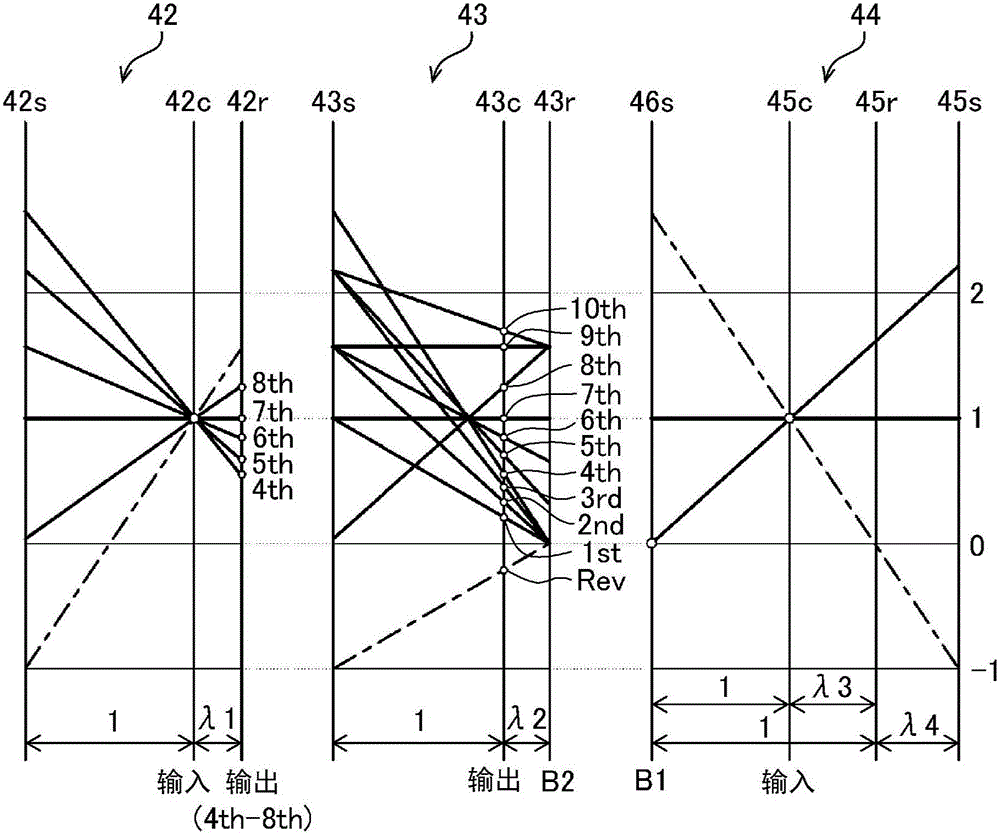
[0024] Below, refer to Figure 1 to Figure 7 Embodiments of the present invention will be described.

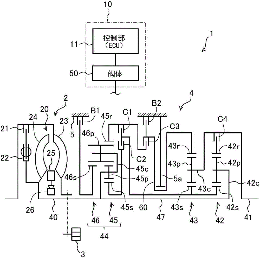
[0025] First, refer to Figure 1 to Figure 3 A schematic configuration of an automatic transmission 1 to which the present invention can be applied will be described. The automatic transmission 1 of the present embodiment is connected to the crankshaft of an unillustrated engine (internal combustion engine) or the rotor of an electric motor as a drive source mounted vertically on the front portion of a rear-wheel drive vehicle, and can receive power from the engine or the like ( Torque) is transmitted to the left and right rear wheels (drive wheels) not shown in the figure. The automatic transmission 1 has a starting device (fluid transmission device) 2 , an oil pump 3 , a speed change mechanism 4 that shifts power transmitted from an engine or the like to an input shaft 40 and transmits it to an output shaft 41 , and a transmission case 5 that accommodates these components...


PUM


Abstract

A control unit is provided such that, when engaging pressure is supplied to both of two working oil chambers to engage a prescribed engaging element and achieve a first speed level, and an engaging element other than the prescribed engaging element is clutched to shift speeds to a second speed level (step S1), the control unit reduces the supply of engaging pressure to one of the two working oil chambers to less than the supply when the first speed level is achieved (step S3).

Description

technical field [0001] The present invention relates to a hydraulic control device of an automatic transmission having a plurality of engagement elements mounted on a vehicle, and specifically relates to a dual-chamber hydraulic servo control device having a plurality of operating oil chambers for one engagement element. The oil pressure control device of the automatic transmission that engages or disengages the engaging member. Background technique [0002] Conventionally, a stepped automatic transmission mounted on a vehicle, for example, uses a hydraulic control device to control the engagement states of a plurality of engagement elements (clutches, brakes), and forms a transmission path in the transmission mechanism for each gear stage to realize multiple transmissions. Gear shift. In such a stepped automatic transmission and a hydraulic control device, a hydraulic servo is used in order to engage or disengage the engagement elements, and as the hydraulic servo, there i...

Claims


Application Information

Patent Timeline
Patent Type & Authority Applications(China)
IPC IPC(8): F16H61/12
CPCF16H61/686F16H2063/303F16H61/061F16H63/3026F16H61/12F16H57/10F16H2057/087F16H2061/1232F16H2200/2023F16H3/663F16H2200/0069F16H2200/201F16H2200/2046F16H61/0021F16H61/0265
Inventor 平井信行前田祥广山口雅路兵藤芳充土田建一
Owner AISIN AW CO LTD
Learn More