Chemical heat regeneration type diesel engine

A technology of chemical heat recovery and diesel engine, which is applied in mechanical equipment, engine components, combustion engines, etc., can solve the problems of high fuel consumption and low efficiency of diesel engines, and achieve the effects of improving combustion efficiency, improving efficiency, and reducing heat dissipation

Inactive Publication Date: 2016-06-01
HARBIN INST OF TECH
View PDF5 Cites 4 Cited by
  • Summary
  • Abstract
  • Description
  • Claims
  • Application Information

AI Technical Summary

Problems solved by technology

[0006] The purpose of the present invention is to provide a new type of diesel engine energy utilization method, which uses the advantages of chemical reheating technology to solve the problems of low efficiency and high fuel consumption of current diesel engines, and at the same time reduces the content of solid particles in exhaust gas by improving combustion efficiency

Method used


Image

  • Chemical heat regeneration type diesel engine

Examples


specific Embodiment approach 1

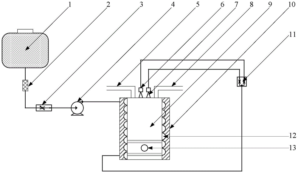
[0018] Specific implementation mode one: the following combination figure 1 Describe this embodiment, the chemical regenerative diesel engine described in this embodiment includes a fuel tank 1, a filter 2, a flow regulating valve 3, a booster pump 4, an intake pipe 5, a liquid fuel nozzle 6, a gaseous fuel nozzle 7, an exhaust Air pipe 8, cylinder 9, switching valve 11, cooling channel 12 and piston 13,

[0019] The top end cover of the cylinder 9 is provided with an intake pipe 5, a liquid fuel nozzle 6, a gaseous fuel nozzle 7 and an exhaust pipe 8; the outer wall of the cylinder 9 is provided with a spiral cooling channel 12; the inner cavity of the cylinder 9 is provided with a piston 13;

[0020] The switching valve 11 is used for switching between the cold fuel oil circuit and the hot fuel oil circuit;

[0021] When the engine is running, the diesel oil flows out from the fuel tank 1 and after being filtered by the filter 2 and regulated by the flow regulating valve 3,...

specific Embodiment approach 2

[0027] Specific Embodiment 2: This embodiment will further describe Embodiment 1, and also includes a ceramic heat insulating layer 10, which is arranged outside the cooling channel 12 to reduce the heat dissipation of high-temperature oil and gas in the cylinder 9 to the environment. Further increase the heat recovery.


PUM


Abstract

The invention discloses a chemical heat regeneration type diesel engine, belongs to the field of internal combustion engines, and solves the problems of lower efficiency and higher oil consumption in a traditional diesel engine. The chemical heat regeneration type diesel engine imitates working principles of a chemical heat regeneration type aloof ramjet and a chemical heat regeneration circulating gas turbine; and diesel is sprayed into a cylinder for burning after finishing the chemical heat regeneration process. When the engine is operated, the diesel flows out from an oil tank to supercharge to form high-pressure diesel after filtration and flow adjustment; the high-pressure diesel flows into a spiral cooling channel to absorb heat generated by burning of a fuel in the cylinder and dispersed to the wall surface of the cylinder; the chemical cracking is generated when protecting the wall surface to generate one part of gaseous micromolecule products; a switching valve is switched to a thermal fuel oil way; high-temperature cracking gas and non-cracked diesel steam enter a gaseous fuel nozzle by the switching valve, and then are sprayed into the cylinder for burning; when the engine is started, as a temperature field is not built, the diesel is still in a liquid state before entering the cylinder; the switching valve is switched to a cold fuel oil way; and the diesel is sprayed into the cylinder after being atomized by a liquid fuel nozzle.

Description

technical field [0001] The invention belongs to the field of internal combustion engines. Background technique [0002] The internal combustion engine is currently the most commonly used form of power, and its exhaust gas is one of the important reasons for the greenhouse effect and air pollution. Among them, diesel engines widely used in trucks, buses, ships, tractors and railway locomotives are regarded by the public as "accomplices" of smog due to their low efficiency and substandard emissions in daily use. At the same time, the ever-increasing demand for oil consumption not only increases the environmental burden of our country, but also increases the international political and military pressure to maintain oil trade. Therefore, it is extremely urgent to improve the efficiency of diesel engines and reduce fuel consumption and exhaust emissions. [0003] As we all know, except for a limited part of the heat of internal combustion engine fuel combustion being converted ...

Claims


Application Information

Patent Timeline
IPC IPC(8): F02B69/04F02M37/00F02M31/16F02M31/14F02M27/00
CPCF02B69/04F02M27/00F02M31/14F02M31/16F02M37/0047
Inventor 鲍文秦江程昆林周伟星张铎
Owner HARBIN INST OF TECH
Why Eureka
Try Eureka