An early dismantling device for steel pipe scaffolding

A scaffolding and steel pipe technology, applied in the field of steel pipe scaffolding, can solve the problems of large application, small degree of freedom of the contact surface, inconvenient operation, etc., and achieve the effects of reducing amortization costs, simple and efficient operation, and stable performance.

Active Publication Date: 2018-01-19
湖南金峰金属构件有限公司
View PDF14 Cites 0 Cited by
  • Summary
  • Abstract
  • Description
  • Claims
  • Application Information

AI Technical Summary

Problems solved by technology

However, there are the following defects: 1. The female head of the connector is connected to the beam at the bottom of the slab and the cross bar at the bottom of the beam. The contact surface is too small and the degree of freedom is large. The displacement of the crossbeam and the crossbar at the bottom of the beam may even affect the stability of the early demolition head
2. To achieve early removal, it is necessary to rotate the sleeve with compass and align the notch with the positioning point. The whole needs to exert a lot of force. When the load on it is too heavy, it is difficult to achieve early removal and the operation is inconvenient
This design has the advantages of being able to adjust the height of the slab and beam formwork at any time as needed, and has the advantages of strong versatility, but the disadvantage is that it cannot easily connect the cross bar and beams and columns of different weights, nor can it install vertical bars at the lower part of the early dismantling device. , Insufficient stiffness, strength and stability

Method used


Image

  • An early dismantling device for steel pipe scaffolding
  • An early dismantling device for steel pipe scaffolding
  • An early dismantling device for steel pipe scaffolding

Examples


Embodiment Construction

[0023] The present invention will be further described below in conjunction with accompanying drawing.

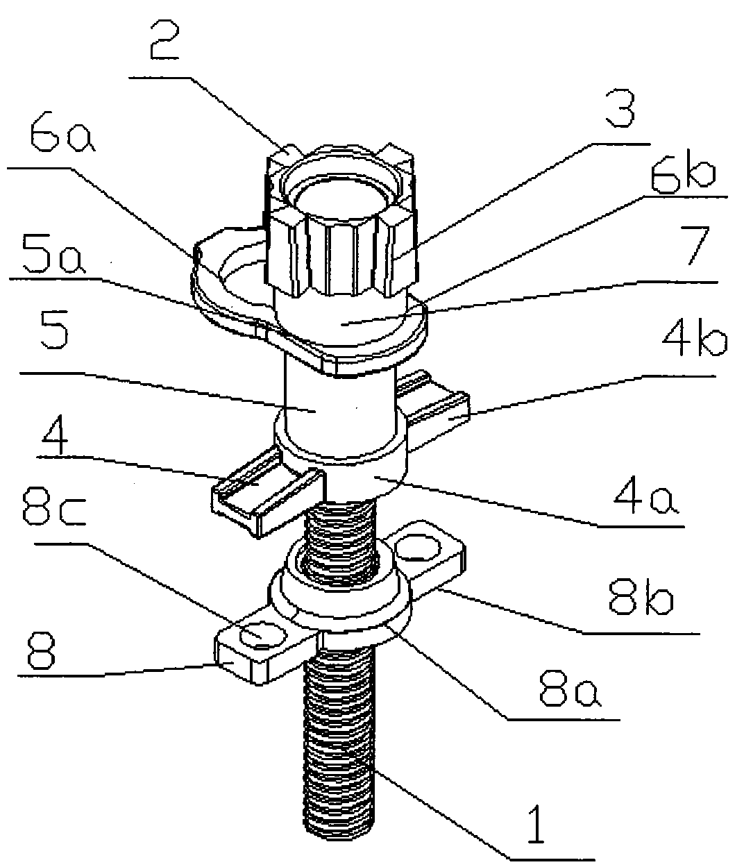
[0024] refer to figure 1 , figure 2 with image 3 As shown, a steel pipe scaffolding early release component provided by the present invention includes an adjusting screw 1 , an early release head and a socket base 2 .

[0025] The surface of the adjusting screw 1 is provided with external threads, and is installed on the top of the vertical rod.

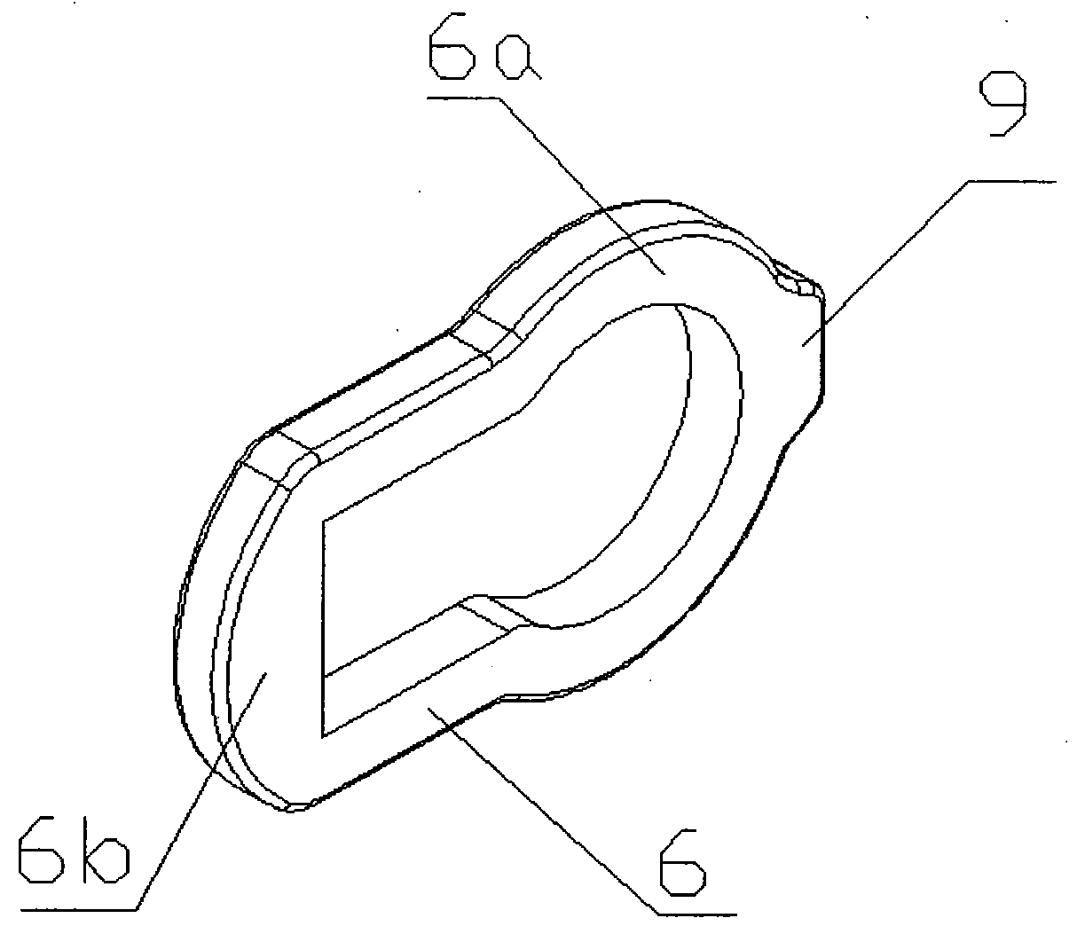
[0026] The early dismantling head includes a bracket 4 , a pipe body 5 and a snap ring 6 . The bracket 4 includes a hollow cylindrical support body 4a and a handle 4b arranged on the support body 4a for rotating the support body 4a. The matching internal thread, the bracket 4 is sleeved on the outside of the adjusting screw 1. The rotating handle 4b drives the bracket 4 to move up and down along the external thread of the adjusting screw 1 to adjust the height of the early dismantling head on the adjusting screw 1 .

[002...


PUM


Abstract

The invention provides an early dismantling device for a steel pipe scaffold, which includes an adjusting screw, an early dismantling head and a socket base. The early detachable head includes a bracket, a tube body and a snap ring. The bracket includes a bracket body and a handle arranged on the bracket body to rotate the bracket body. The bracket is sleeved outside the adjusting screw. The tube body is hollow cylindrical and four card slots are evenly and symmetrically arranged in the circumferential direction. The card slots are formed by the tube body. Inwardly recessed to form a flat inner wall, the pipe body is arranged above the bracket, and the snap ring is formed by interconnecting a non-closed large ring and a small ring, the inner diameter of the large ring is not smaller than the outer diameter of the pipe, and the inner wall of the small ring is flat and It is clamped between the three card slots. The invention can flexibly adjust the position of the early dismantling head on the adjusting screw, and can flexibly adjust the direction of the early dismantling head according to the needs of use. When it is necessary to realize the early dismantling, only a small force needs to be applied, and the operation is simple and efficient. The invention has the advantages of simple structure, convenient loading and unloading, stable performance, safety and reliability.

Description

technical field [0001] The invention relates to the field of steel pipe scaffolding, in particular to an early dismantling component and device for steel pipe scaffolding. Background technique [0002] In the concrete pouring construction of buildings, pouring materials such as cement are all poured in the building formwork erected according to the design requirements, and the formwork support system mostly adopts two methods: the first one is referred to as the publication number CN203684683, named "a A patent document for an early dismantling head structure device", which discloses an early dismantling head structure device, including a steel pallet, an inner steel pipe, a screw rod and a screw nut, and the inner steel pipe is arranged between the steel pallet and the screw rod , the screw nut is set on the screw and can slide along the screw. Compared with the commonly used fastener-type scaffolding and other technical solutions, this utility model has two advantages: 1....

Claims


Application Information

Patent Timeline
Patent Type & Authority Patents(China)
IPC IPC(8): E04G25/04E04G11/48
Inventor 杨棣柔
Owner 湖南金峰金属构件有限公司
Why Eureka
Try Eureka