Core mold for manufacturing intermediate tubular shaft of coupler and manufacturing method of intermediate tubular shaft of coupler

A manufacturing method and coupling technology, which is applied in the field of mandrel and coupling intermediate tube shaft manufacturing, can solve the problem of the decrease of the torsional strength of the intermediate tube shaft, the difficulty in maintaining the coaxiality of the intermediate tube shaft, and the difficulty in processing the tapered surface, etc. problems, to improve production efficiency, avoid the decline in coaxiality, and save the effect of tapered surface processing

Active Publication Date: 2016-06-01
ZHUZHOU TIMES NEW MATERIALS TECH
View PDF8 Cites 6 Cited by
  • Summary
  • Abstract
  • Description
  • Claims
  • Application Information

AI Technical Summary

Problems solved by technology

For the middle pipe shaft with a relatively long length, the length of the mold to be wound is relatively large during the winding process, and the load of the mold gradually increases during the winding process. The concentricity of the intermediate tube axis, and the conical surface processing process will easily lead to fiber damage, which will reduce the torsional strength of the intermediate tube axis. The conical surface processing is difficult and the precision is low, and it is difficult to maintain the coaxiality of the intermediate tube axis

Method used


Image

  • Core mold for manufacturing intermediate tubular shaft of coupler and manufacturing method of intermediate tubular shaft of coupler
  • Core mold for manufacturing intermediate tubular shaft of coupler and manufacturing method of intermediate tubular shaft of coupler
  • Core mold for manufacturing intermediate tubular shaft of coupler and manufacturing method of intermediate tubular shaft of coupler

Examples


Embodiment Construction

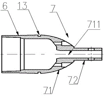
[0028] The present invention will be described in detail below in conjunction with the accompanying drawings.

[0029] Such as Figure 1 to Figure 4 As shown, the core mold for manufacturing the intermediate tube shaft of the coupling includes a static mold 1 and a moving mold 2, wherein the static mold 1 includes a static mold cylinder 3, which is integrally formed with the static mold cylinder 3 on the left side of the static mold cylinder 3 The static mold head 4 and the static mold shaft 5 fixedly installed in the middle of the static mold head 4, the junction of the static mold cylinder 3 and the static mold head 4 is provided with a cutting seam 12, wherein the movable mold 2 includes a dynamic The mold cylinder 6, the movable mold head 7 integrally formed with the movable mold cylinder 6 on the right side of the movable mold cylinder 6, the joint between the movable mold cylinder 6 and the movable mold head 7 is provided with two cutting seams 13. The inside of the sta...


PUM


Abstract

A core mold for manufacturing an intermediate tubular shaft of a coupler comprises a static mold and a movable mold. The static mold and the movable mold are detachably assembled. The static mold comprises a static mold cylinder, a static mold seal head and a static mold shaft fixedly installed in the middle of the static mold seal head. A first cutting seam is formed in the joint of the static mold cylinder and the static mold seal head. The movable mold comprises a movable mold cylinder and a movable mold seal head. A second cutting seam is formed in the joint of the movable mold cylinder and the movable mold seal head. The static mold and the movable mold are assembled together, the static mold shaft penetrates through the static mold and the movable mold, and the static mold cylinder and the movable mold cylinder are assembled to form an intermediate cylinder; the inner surface of the intermediate cylinder is a cylindrical surface, the two ends of the outer surface of the intermediate cylinder are conical surfaces, and the middle portion of the outer surface of the intermediate cylinder is a cylindrical surface. The core mold does not deform in the wind-forming process of the intermediate tubular shaft, the internal conical surface is formed while the intermediate tubular shaft is formed through winding, and the procedure of conical surface machining is omitted, so that the production cost is reduced, the production efficiency is improved, and the coaxiality of the intermediate tubular shaft is guaranteed. The invention further provides a manufacturing method of the intermediate tubular shaft of the coupler.

Description

technical field [0001] The invention relates to a core mold for manufacturing an intermediate tubular shaft and a manufacturing method for the intermediate tubular shaft, in particular to a core mold for manufacturing a coupling intermediate tubular shaft and a manufacturing method for the coupling intermediate tubular shaft. Background technique [0002] As an extremely critical part of the wind turbine, the coupling is located between the wind power gearbox and the generator, and mainly plays the role of transmitting torque. The coupling is composed of an intermediate tube shaft, a flange, and a brake disc. The intermediate tube The shaft is the core component of the coupling. The intermediate tube shaft of composite material with good electrical insulation performance and excellent fatigue performance has gradually replaced the intermediate tube shaft of alloy steel material and is applied to the coupling. The existing composite material intermediate pipe shaft and the...

Claims


Application Information

Patent Timeline
Patent Type & Authority Applications(China)
IPC IPC(8): B29C70/32
Inventor 黄河王虎李再轲秦中正王亚平
Owner ZHUZHOU TIMES NEW MATERIALS TECH
Why Eureka
Try Eureka