
a combined evaporator

An evaporator and combined technology, which is applied in the field of combined evaporators, can solve the problems of large space occupation and inconvenient sealing, and achieve the effects of efficient use of space, convenient installation, and increased heating area

Active Publication Date: 2017-09-08
温州伟明环保能源有限公司
View PDF4 Cites 0 Cited by
  • Summary
  • Abstract
  • Description
  • Claims
  • Application Information

AI Technical Summary

Problems solved by technology

The structure occupies a large space and is inconvenient to seal

Method used


Image

  • a combined evaporator
  • a combined evaporator
  • a combined evaporator

Examples


Embodiment Construction

[0029] The present invention will be further described below in conjunction with the accompanying drawings.

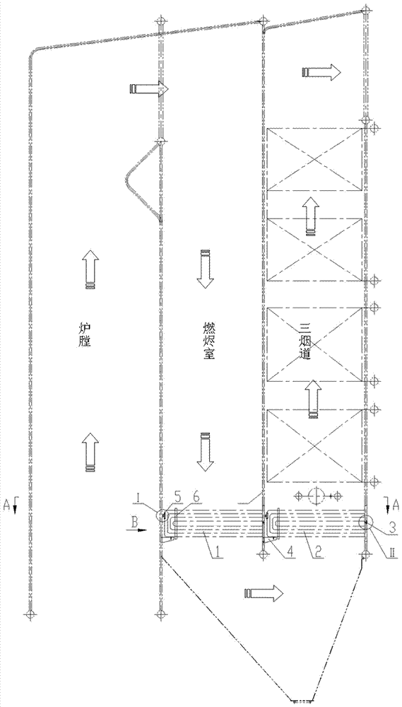
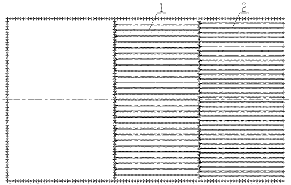
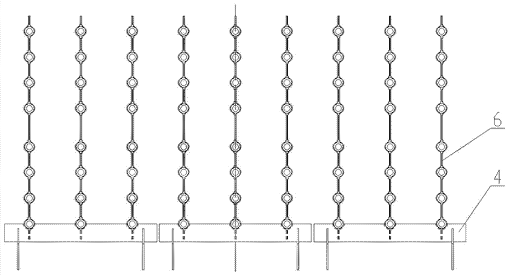
[0030] like Figure 1-5 As shown, the combined evaporator of the present invention includes a first evaporator tube bundle 1 , a second evaporator tube bundle 2 , a bracket 4 and a bracket 5 . The first evaporator tube bundle 1 is arranged at the bottom of the ember chamber, and the second evaporator tube bundle 2 is arranged at the bottom of the three flues. The first evaporator tube bundle and the second evaporator tube bundle are composed of multiple rows of parallel tube bundles. The inlet and outlet ends of the tube bundles of the first and second evaporators are directly connected to the corresponding water-cooled wall tubes, and slots are made on the water-cooled wall tubes between the inlets and outlets of the tube bundles of the first and second evaporators, and the throttling orifice plate 3 is installed. The other ends of the tube bundles of the first and s...


PUM


Abstract

The invention belongs to the technical field of boiler parts and particularly relates to a combined evaporator. The combined evaporator structurally comprises a first evaporator tube bundle, a second evaporator tube bundle, a support and a bracket. The first evaporator tube bundle is distributed at the bottom of a burnout chamber, the second evaporator tube bundle is arranged at the bottoms of three flues, the inlet and outlet ends of the evaporator tube bundles are directly connected with corresponding water-cooling wall tubes, grooves are formed in the water-cooling wall tubes between inlets and outlets, and throttle orifice plates are installed in the grooves. The other end of each tube bundle is fixed to the water-cooling wall on the other side through the support and the bracket. By means of the structure, inlet smoke temperature of a superheater can be effectively lowered, limited space is fully used, the heating area is effectively increased, and the combined evaporator is compact in structure, convenient to install and suitable for distribution of heating faces of various boilers.

Description

technical field [0001] The invention belongs to the technical field of boiler components, and in particular relates to a combined evaporator. Background technique [0002] With the continuous improvement of people's living standards, the calorific value of domestic waste is also increasing. In order to cope with changes in the calorific value of waste, the waste incineration boiler needs to increase the heating surface accordingly. Usually a large boiler chamber includes a furnace, an ember chamber, and three flues, and the heating surfaces are generally arranged in the three flues. There are two common ways to increase the heating surface: raising the overall height of the boiler, or reducing the pitch of the heating surface. However, increasing the boiler height will greatly increase the construction cost, while reducing the pitch will easily accumulate dust and coke, which will cause corrosion to the heating surfaces such as high-temperature superheaters. In addition, ...

Claims


Application Information

Patent Timeline
Patent Type & Authority Patents(China)
IPC IPC(8): F22B31/08F22B37/10F22B37/20
CPCF22B31/08F22B37/10F22B37/20
Inventor 项光明李荣刘超
Owner 温州伟明环保能源有限公司
Learn More