Eureka AIR delivers breakthrough ideas for toughest innovation challenges, trusted by R&D personnel around the world.

Continuous internal heating double-barrel pyrolysis furnace for solid organic matter

A technology of solid organic matter and cracking furnace, which is applied in coking ovens, direct heating dry distillation, and preparation of liquid hydrocarbon mixtures. It can solve the problems of potential safety hazards, low processing capacity, and high labor intensity, and achieve reasonable energy utilization and high processing capacity. Great effect with low labor intensity

Active Publication Date: 2018-01-09
青岛伊诺威能源化工新技术有限公司
View PDF6 Cites 0 Cited by
  • Summary
  • Abstract
  • Description
  • Claims
  • Application Information

AI Technical Summary

Problems solved by technology

[0004] The purpose of the present invention is to change the existing rotary kiln type cracking furnace which adopts external rotary heating, high energy consumption, serious pollution, low processing capacity, high cost, high labor intensity and hidden safety hazards caused by intermittent operation, and provide a A continuous internal heating double-barrel pyrolysis furnace for solid organic matter

Method used


Image

  • Continuous internal heating double-barrel pyrolysis furnace for solid organic matter
  • Continuous internal heating double-barrel pyrolysis furnace for solid organic matter
  • Continuous internal heating double-barrel pyrolysis furnace for solid organic matter

Examples


Embodiment Construction

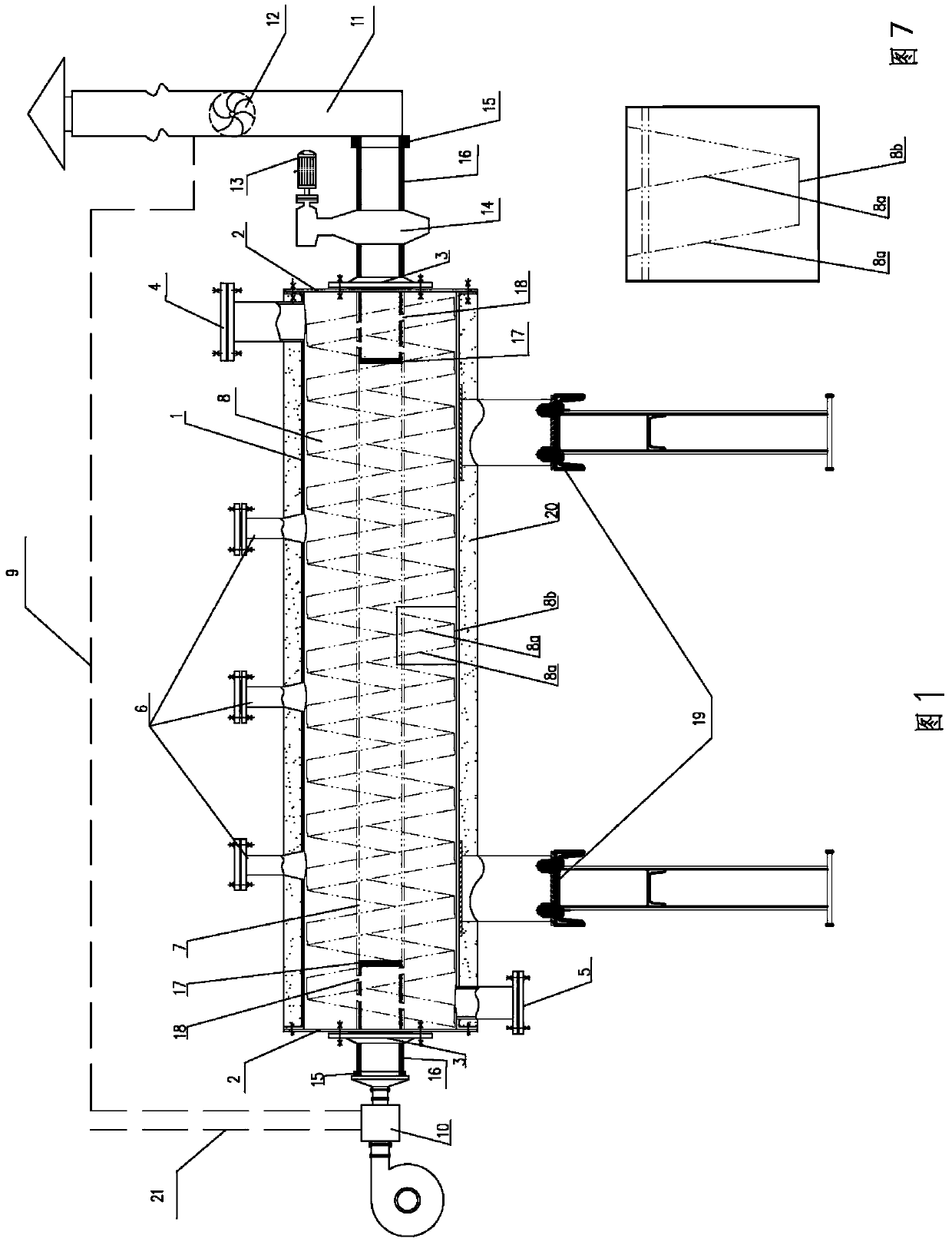
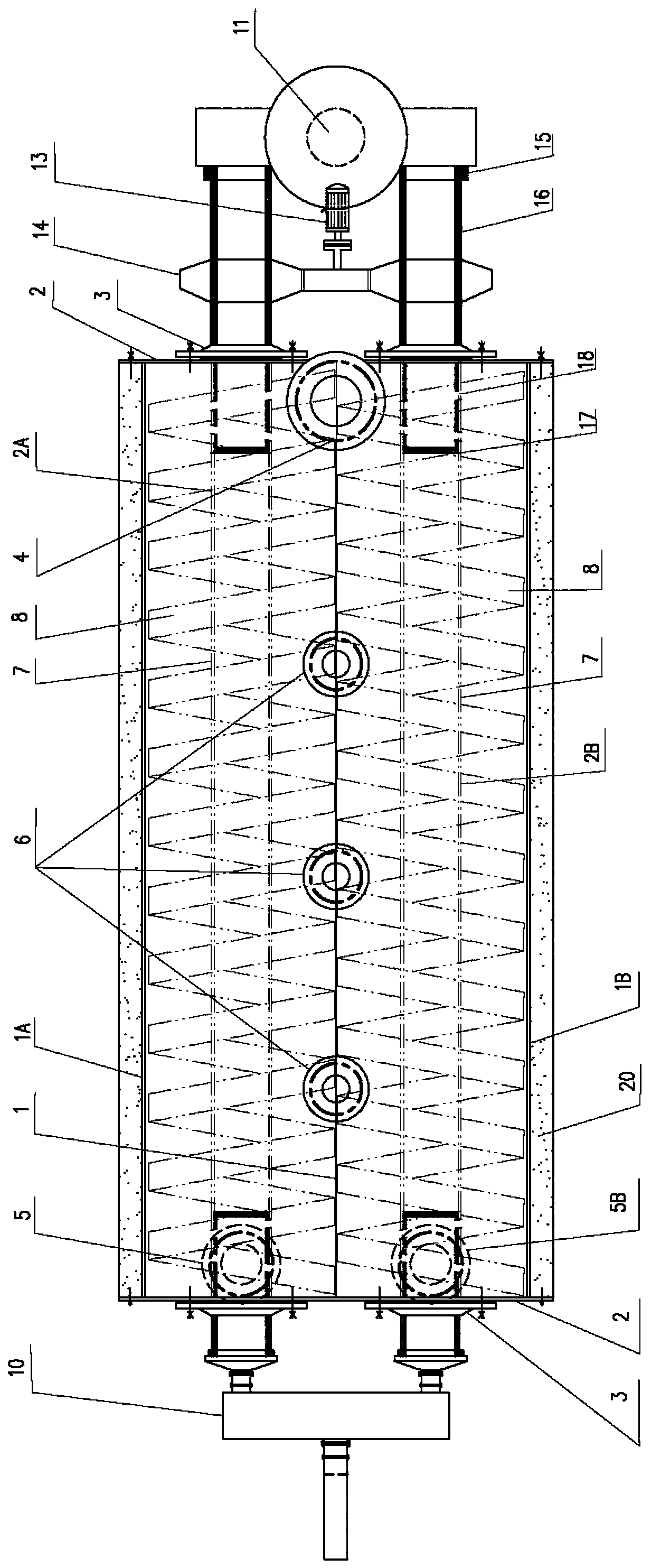
[0016] Such as Figure 1-7 , a continuous internal heat type solid organic double cylinder cracking furnace is characterized in that the cracking furnace includes double cylinders 1 supported by brackets 19 and placed horizontally, and the double cylinders 1 include left and right cylindrical cylinders arranged side by side. The cylinders (1A, 1B), the left and right cylinders (1A, 1B) have the same structure and the axes are parallel to each other, and the left and right cylinders (1A, 1B) are tangent to each other so that the two cylinders (1A, 1B ) are connected to each other, the double cylinder 1 also includes an upper surface 1C located on the upper part of the left and right cylinders (1A, 1B), and the upper surface 1C is located between the left and right cylinders (1A, 1B) , and are respectively tangent to the tops of the left and right cylinders (1A, 1B), the upper surface 1C and the left and right cylinders (1A, 1B) are enclosed to form a space, which contains three...


PUM


Abstract

A continuous internal heating type double-barrel cracking furnace for solid organic matter is of a fixed horizontal double-barrel-body structure. Continuous feeding is performed on the upper portion of one end of each barrel body. Continuous slag discharging is performed on the lower portion of the other end of each barrel body. The upper portion of each barrel body is provided with a plurality of gas outlets. Two rotors are arranged in the dual barrel bodies side by side. While the rotors are used for heating materials in the barrel bodies in a dividing-wall mode, the materials are propelled and stirred rotationally. Each rotor is composed of a shaft barrel and a screw band, and each screw band is of a hollow structure. High-temperature flue gas firstly enters the shaft barrels and then enters inner cavities of the screw bands through flow guiding holes, the flue gas rotates along with the rotating barrels in the inner cavities of the screw bands and spirally flows along the inner cavities of the screw bands at the same time, heat is fully released, the materials are heated, and then the flue gas enters the shaft barrels to be exhausted. The flue gas and the materials are in countercurrent dividing-wall heat transfer, temperature difference is large, smoke exhaust temperature is low, heating is uniform, cracking gas is exhausted in time, secondary cracking is avoided, and the oil yield is high. The furnace is scientific and reasonable in structure and technology, high in machining capacity, low in cost, capable of achieving energy conservation and environment protection, safe, reliable and low in labor intensity, pollution caused by combustion of dioxin is avoided, resources are reasonably utilized, and market popularization value is great.

Description

technical field [0001] The invention relates to a continuous internal heating double-barrel cracking furnace for solid organic matter, which belongs to the field of cracking solid organic matter and is used for thermal cracking or carbonization of solid organic matter. Background technique [0002] Every year, a large amount of solid organic matter needs to be processed in our country. Solid organic matter generally includes plastic, rubber, straw, wood, coal powder, residual oil, etc., especially solid organic matter such as waste plastic and waste rubber contained in the growing urban waste is difficult to degrade. The general method of these solid organic matter is direct incineration, which only recovers heat and produces pollutants such as dioxins, which are generally resisted by the local people, resulting in unreasonable use of resources; similarly, burning straw in rural areas pollutes the air and wastes resource. The thermal cracking method is used to process these...

Claims


Application Information

Patent Timeline
Patent Type & Authority Patents(China)
IPC IPC(8): C10B49/04C10G1/00
CPCC10B49/04C10G1/00C10G2300/1003
Inventor 刘运良李贤辉徐洪刘斯佳孙戈
Owner 青岛伊诺威能源化工新技术有限公司
Why Eureka
Eureka Blog
Learn More