
Sewage treatment method with enhanced denitrification and dephosphorization functions

A sewage treatment method and technology for denitrification and phosphorus removal, applied in water/sewage treatment, biological water/sewage treatment, water/sewage multi-stage treatment, etc. Phosphorus requirements, mud age contradictions and other issues, to achieve the effect of significant sludge reduction, strong shock load resistance, and carbon source reduction

Inactive Publication Date: 2016-05-25
SHENZHEN PANGU ENVIRONMENTAL PROTECTION TECH CO LTD
View PDF5 Cites 3 Cited by
  • Summary
  • Abstract
  • Description
  • Claims
  • Application Information

AI Technical Summary

Problems solved by technology

[0003] A 2 The / O process is a typical process for nitrogen and phosphorus removal, which mainly includes three stages of anaerobic, anoxic and aerobic. For low C / N sewage, due to the problems of carbon source competition and sludge age conflicts in the sewage treatment process , causing A 2 The / O process is difficult to meet the requirements of denitrification and phosphorus removal at the same time
Aiming at low-carbon issues, people in A 2 In the / O process, the technology of measuring flow and phosphorus removal is added, which not only reduces the load of subsequent microorganisms to absorb phosphorus, but also reduces the carbon source consumed by microorganisms when absorbing phosphorus; 2 In the / O process, enhanced denitrification technologies have been added, such as simultaneous nitrification and denitrification or denitrification and phosphorus absorption. Although these two technologies have increased the removal effect of nitrogen and phosphorus removal to a certain extent, the treated sewage has not yet reached Emission Standards

Method used


Image

  • Sewage treatment method with enhanced denitrification and dephosphorization functions

Examples


Embodiment 1

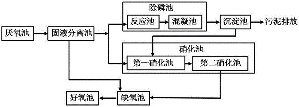
[0029] The phosphorus removal tank in the step S2 is composed of a reaction tank and a coagulation tank, and 10% of the supernatant produced by the solid-liquid separation tank is introduced into the reaction tank for treatment and then into the coagulation tank for processing. During the process, the reaction tank and the coagulation tank need to be aerated.

[0030] The dephosphorization agent added in the reaction tank is ferric chloride, and it needs to be fully stirred during the dosing process, so that the phosphate substance in the reaction tank is precipitated in the form of iron phosphate; the coagulation tank is added The coagulant used is polyacrylamide, and the polyacrylamide can absorb the ferric phosphate precipitate that enters the coagulation tank, so that it can be precipitated as flocculent particles with larger particles, and the ferric phosphate precipitate that is beneficial to be formed can be The settling tank is completely settled, so that the ferric ph...

Embodiment 2

[0034] As the sewage treatment method for efficient denitrification and phosphorus removal described in Example 1, the difference of this embodiment is that the phosphorus removal tank in the step S2 is composed of a reaction tank and a coagulation tank, and the solid-liquid separation tank 12% of the supernatant produced is introduced into the reaction tank for treatment and then into the coagulation tank for treatment. During the treatment, the reaction tank and the coagulation tank need to be aerated.

[0035] The dephosphorization agent added in the reaction tank is ferric sulfate, and it needs to be fully stirred during the dosing process, so that the phosphate substance in the reaction tank is precipitated in the form of iron phosphate; the mixing tank added in the coagulation tank The coagulant is polyaluminum chloride, and the polyaluminum chloride can absorb the ferric phosphate precipitation entering the coagulation tank, so that it can be precipitated in flocculent f...

Embodiment 3

[0037] As the sewage treatment method for efficient denitrification and phosphorus removal described in Example 2, the difference of this embodiment is that the phosphorus removal tank in the step S2 is composed of a reaction tank and a coagulation tank, and the solid-liquid separation tank 15% of the generated supernatant is introduced into the reaction tank for treatment and then into the coagulation tank for treatment. During the treatment, the reaction tank and the coagulation tank need to be aerated.

[0038] The dephosphorization agent added in the reaction tank is lime, and it needs to be fully stirred during the dosing process, so that the phosphate substance in the reaction tank is precipitated in the form of calcium phosphate; the coagulation added in the coagulation tank The agent is polyferric sulfate, and the polyferric sulfate can be adsorbed into the calcium phosphate precipitate in the coagulation tank, so that it is precipitated with larger particles of floccul...


PUM


Abstract

The invention provides a sewage treatment method with enhanced denitrification and dephosphorization functions. The method is implemented by increasing dephosphorization and nitrification techniques on the basis of the anaerobic-anoxic-aerobic technique. The method specifically comprises the following steps: S1: introducing sewage treated by an anaerobic tank into a solid-liquid separation tank; S2: introducing a sludge-water mixture generated by the solid-liquid separation tank into an anoxic tank, introducing part of the generated supernatant into a dephosphorization tank, and introducing the rest of the generated supernatant into a nitrification tank; S3: introducing the mixed solution treated by the dephosphorization tank into a precipitation tank, discharging sludge generated by the precipitation tank, and introducing the generated supernatant into the nitrification tank; and S4: sequentially introducing the nitrification solution treated by the nitrification tank into the anoxic tank and aerobic tank for treatment. According to the method, the dephosphorization tank and the nitrification are separated, so that the dephosphorization and denitrification are not mutually influenced on the premise of implementing the dephosphorization and denitrification functions, thereby keeping the stability of the sewage treatment system.

Description

technical field [0001] The invention relates to the field of sewage treatment, in particular to a sewage treatment method for strengthening nitrogen and phosphorus removal. Background technique [0002] As more and more nitrogen and phosphorus nutrients enter the nearby water bodies through urban sewage, the problem of water body nutrition becomes more and more prominent. Therefore, how to remove nitrogen and phosphorus substances in sewage has become an unavoidable problem. [0003] A 2 The / O process is a typical process for nitrogen and phosphorus removal, which mainly includes three stages of anaerobic, anoxic and aerobic. For low C / N sewage, due to the problems of carbon source competition and sludge age conflicts in the sewage treatment process , causing A 2 It is difficult for the / O process to meet the requirements of denitrification and phosphorus removal at the same time. Aiming at low-carbon issues, people in A 2 In the / O process, the technology of measuring ...

Claims


Application Information

Patent Timeline
Patent Type & Authority Applications(China)
IPC IPC(8): C02F9/14
CPCC02F9/00C02F1/5236C02F1/56C02F3/02C02F3/28C02F3/302C02F3/308C02F2001/007
Inventor 赵建树马艳辉周鸿波宋庆
Owner SHENZHEN PANGU ENVIRONMENTAL PROTECTION TECH CO LTD
Learn More