
Power supply aging test circuit

A technology of aging test and power supply, which is applied in the field of power supply aging test. It can solve the problems of large influence of switching power supply, contact vibration, burning of switching power supply, etc., and achieves the effect of wide application range, convenient operation and simple circuit structure.

Inactive Publication Date: 2016-05-18
EAST GRP CO LTD
View PDF8 Cites 8 Cited by
  • Summary
  • Abstract
  • Description
  • Claims
  • Application Information

AI Technical Summary

Problems solved by technology

[0006] In the case that the output of the switching power supply is loaded, the intermittent aging test is commonly used, that is, the input voltage on-off test. Usually, a time relay is used to control an AC contactor to achieve the on-off control of the input voltage. However, the AC contactor The switch is a mechanical switch. During the on-off process, the contacts will vibrate, which may cause the switching power supply to burn out in the input rectification part, which has a greater impact on the switching power supply.

Method used


Image

  • Power supply aging test circuit

Examples


Embodiment Construction

[0026] The present invention will be further described in conjunction with the following examples.

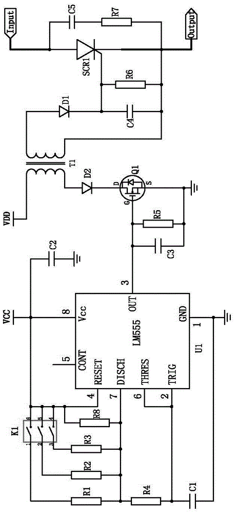
[0027] An aging test circuit for a power supply of this embodiment includes a square wave generator, the input end of the square wave generator is connected to an RC oscillator circuit capable of changing the oscillation frequency, and the output end of the square wave generator is connected to According to the output of the square wave sounder, the control circuit that controls whether the voltage input to the power supply under test is connected to the power supply under test.

[0028] The RC oscillating circuit capable of changing the oscillation frequency is an RC oscillating circuit capable of changing the resistance value of the resistance participating in the oscillation, including a dial switch and a resistor array, and the dial switch is used to control the resistance of the resistor array connected to the RC oscillator circuit value.

[0029] The square wave generator is a ...


PUM


Abstract

Provided is a power supply aging test circuit, relating to the power supply aging test technical field. The power supply aging test circuit comprises a square-wave generator; the input terminal of the square-wave generator is in connection with an RC oscillation circuit, and the output terminal of the square-wave generator is in connection with a control circuit; the control circuit comprises a silicon controlled rectifier diode; if the silicon controlled rectifier diode is conducted, the voltage inputted to the power supply to be detected is conducted to the power supply to be detected; if the silicon controlled rectifier diode is cut off, the voltage inputted to the power supply to be detected is cut off from the power supply to be detected. Accordingly, through the square-wave generator and the silicon controlled rectifier diode, the on and off control of the input voltage in a power supply aging test can be realized, thereby avoiding partial burning of a switching power supply in an input rectification portion possibly caused by using an alternating current contactor; the power supply aging test circuit has a simple structure, and can safely perform power supply aging test, and cause less damage to a power supply in test.

Description

technical field [0001] The invention relates to the technical field of power supply aging test, in particular to a power supply aging test circuit. Background technique [0002] In the field of power supplies, aging tests are required before leaving the factory. Generally, there are three methods for aging tests. [0003] The first way is normal aging: the power supply is directly loaded and energized for aging. The uninterrupted continuous working time of the power supply is more than one month, no failure, no burning phenomenon, and the parameters are stable, it is considered qualified. [0004] The second method is intermittent aging: the power supply is loaded with intermittent energization aging test, and the power supply is powered on and off continuously under the condition of load to test the impact resistance of the power supply. If the aging time is more than one month, there is no failure, no burning phenomenon, and the parameters are stable, it is considered qu...

Claims


Application Information

Patent Timeline
Patent Type & Authority Applications(China)
IPC IPC(8): G01R31/40
CPCG01R31/40
Inventor 贾芳
Owner EAST GRP CO LTD
Learn More