
Method and device for controlling ductility of FRP reinforcing structure

A technology for reinforcing structures and FRP sheets, applied in building construction, construction, building maintenance, etc., can solve the problems of increased economic cost, low FRP utilization rate, life safety threat, etc., and achieve the effect of improving utilization rate

Active Publication Date: 2016-05-11
SHENZHEN UNIV
View PDF5 Cites 3 Cited by
  • Summary
  • Abstract
  • Description
  • Claims
  • Application Information

AI Technical Summary

Problems solved by technology

However, a large number of current experimental studies have shown that the FRP-concrete bond interface is relatively fragile, and it is very consistent in the peeling failure with the typical failure form of FRP peeling from the concrete.
There are significant disadvantages in this destruction: (1) FRP utilization rate is low, and FRP will be peeled off from the concrete interface when only reaching about 30% utilization rate, which is a huge problem for FRP materials with very high strength. waste, but also increases the economic cost; (2) the ductility is poor, and the failure mode belongs to brittle failure
Brittle failure is a kind of sudden failure. The time from the failure to the collapse of the building is extremely short, which is prohibited in engineering, because when the reinforced structure is affected by external effects, such as changes in the use of houses, earthquakes, etc., once the structure occurs If the house is brittle, it will collapse suddenly, and people will have no time to escape, which will pose a great threat to people's life safety.
Although there are methods to deal with the problem of FRP utilization, the improvement of FRP ductility is still uncontrollable, and the controllability of FRP ductility improvement is of great significance to actual production

Method used


Image

  • Method and device for controlling ductility of FRP reinforcing structure
  • Method and device for controlling ductility of FRP reinforcing structure
  • Method and device for controlling ductility of FRP reinforcing structure

Examples


Embodiment Construction

[0030] The following will clearly and completely describe the technical solutions in the embodiments of the present invention with reference to the accompanying drawings in the embodiments of the present invention. Obviously, the described embodiments are only some, not all, embodiments of the present invention. Based on the embodiments of the present invention, all other embodiments obtained by persons of ordinary skill in the art without making creative efforts belong to the protection scope of the present invention.

[0031] The object of the present invention is to provide a method and device for controlling the ductility of FRP reinforced structures with controllable ductility.

[0032] In order to make the above objects, features and advantages of the present invention more comprehensible, the present invention will be further described in detail below in conjunction with the accompanying drawings and specific embodiments.

[0033] Such asfigure 1 As shown, the overall s...


PUM


Abstract

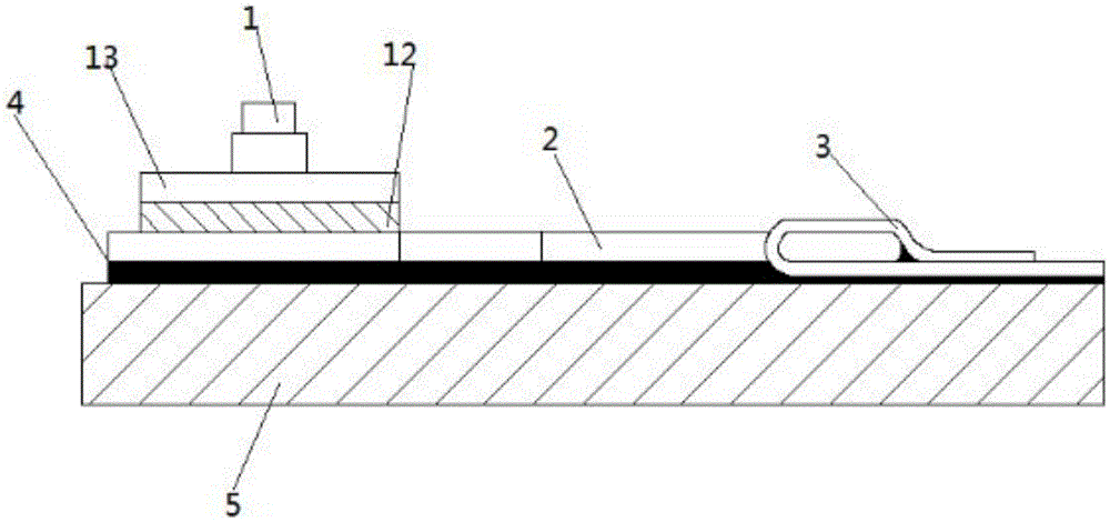
The invention discloses a method and device for controlling the ductility of an FRP reinforcing structure. The FRP reinforcing structure comprises an end anchoring device, an FRP sheet, a friction piece, a rigid cover plate, an expansion bolt and an adhesion agent. The end anchoring device is formed by machining a low-carbon steel plate and provided with an anchoring segment, a deformation segment and a connecting segment. Two long round holes are formed in the anchoring segment. The rigid cover plate and the friction piece are both provided with two round holes. The round holes coincide with the first ends of the long round holes. The shortest distance from the round holes to the second ends of the long round holes is S. The width of the deformation segment is variable. The expansion bolt sequentially penetrates the two round holes of the rigid cover plate, the two round holes of the friction piece and the long round holes of the anchoring segment and is anchored into a structure to be reinforced; friction force is generated between the end anchoring device and the friction piece. Because the device is provided with a friction sliding segment S, and the ductility of the FRP reinforcing structure is controllable.

Description

technical field [0001] The invention relates to the field of FRP reinforcement, in particular to a method and device for controlling the ductility of FRP reinforcement structures. Background technique [0002] Fiber Reinforced Polymer / Plastic (FRP) is widely used in structural reinforcement due to its outstanding advantages such as light weight, high strength, corrosion resistance, and convenient processing. At present, the most widely used and most in-depth research in the world is the external FRP reinforcement technology, also known as EB-FRP reinforcement technology. The method of EB-FRP reinforcement technology is to directly paste the FRP sheet to the structure to be reinforced with epoxy resin, so that the load on the structure will be transferred to the FRP material through the epoxy resin adhesive, so that the FRP Share the unbearable load for the original structure, and achieve the effect of reinforcement through this method. It is not difficult to see that the b...

Claims


Application Information

Patent Timeline
IPC IPC(8): E04G23/02
CPCE04G23/0218E04G2023/0251E04G2023/0262
Inventor 周英武范志恒
Owner SHENZHEN UNIV
Learn More