Shielding cover assembly

A component and mask technology, applied in ion implantation plating, metal material coating process, coating and other directions, can solve the problem of color mixing, solder joint failure, fine metal mask and array glass substrate can not be well fitted and other problems to achieve the effect of eliminating bad folds, improving accuracy and reducing solder joint failures

Inactive Publication Date: 2016-05-11
AU OPTRONICS CORP
View PDF0 Cites 7 Cited by
  • Summary
  • Abstract
  • Description
  • Claims
  • Application Information

AI Technical Summary

Problems solved by technology

However, due to the slender metal wire of the fine metal mask and the tensile force of the clip, wavy wrinkles are likely to appear on the surface of the fine metal mask, which has a negative impact on subsequent measurement, welding, and panel yield.
For example, wrinkling means that the same mask strip is uneven, then the mask strip does not fit the frame well, and where it does not fit, the solder joints will fail
In addition, excessively large wrinkles will cause the fine metal mask and the array glass substrate to not fit well in the subsequent process, causing troubles in color mixing (colormura)

Method used


Image

  • Shielding cover assembly
  • Shielding cover assembly
  • Shielding cover assembly

Examples


Embodiment Construction

[0020] In order to make the technical content disclosed in this application more detailed and complete, reference may be made to the drawings and the following various specific embodiments of the present invention, and the same symbols in the drawings represent the same or similar components. However, those skilled in the art should understand that the examples provided below are not intended to limit the scope of the present invention. In addition, the drawings are only for schematic illustration and are not drawn according to their original scale.

[0021] The specific implementation manners of various aspects of the present invention will be further described in detail below with reference to the accompanying drawings.

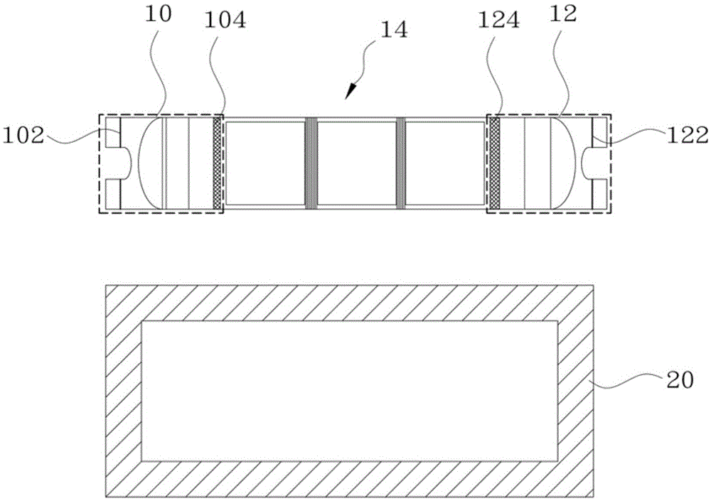
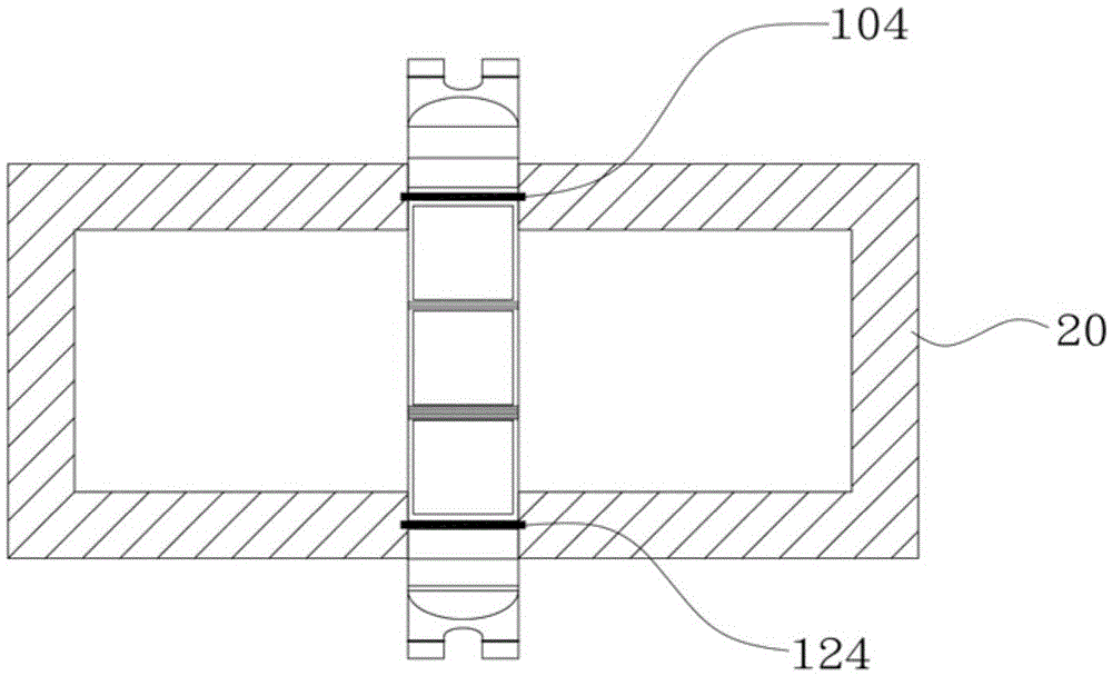
[0022] Figure 1A An exploded schematic diagram showing a fine metal mask and a metal frame of a mask assembly in the prior art before fixing. Figure 1B show Figure 1A Schematic diagram of the state of the fine metal mask and metal frame after fixing.

...


PUM

PropertyMeasurementUnit
thicknessaaaaaaaaaa

Abstract

The invention provides a shielding cover assembly. The shielding cover assembly comprises a fine metal shielding cover and a metal frame, wherein the fine metal shielding cover is fixed on the metal frame, and provided with two stretching areas and a pattern area; and the stretching areas are located at the two opposite sides of the pattern area respectively, wherein each stretching area comprises a semi-arc-shaped hollow part, and stress distribution during a stretching process is improved by virtue of the hollow parts. Compared with the prior art, according to the invention, one semi-arc-shaped hollow part is formed through cutting on each stretching area of the fine metal shielding cover, and stress can be reduced by virtue of the hollow parts, so that tension during a stretching process is much uniformly distributed on the surface of the fine metal shielding cover. In addition, according to the invention, wrinkles during a netting process can be reduced or eliminated, thus the accuracy of alignment measurement is improved, and the possibility of welding spot failure during a welding process is reduced.

Description

technical field [0001] The invention relates to a metal mask manufacturing process, in particular to a mask assembly comprising a fine metal mask and a metal frame. Background technique [0002] In the current patterning process, various patterned film layers are usually formed through a mask composed of a plurality of mask strips and a coating process. Here, the mask is a thin metal plate that is etched to form a plurality of elongated metal lines, and the gaps between these metal lines are used as opening areas during the coating process. Generally speaking, because the metal wire is quite slender and easy to twist and deform, there are usually stretching areas on both sides of the masking strip. Pre-tension is applied to make the metal wire taut transversely. In this way, the metal line can be kept basically straight so that the opening area maintains the correct shape and position, and it can resist the expansion caused by the temperature rise during coating, as well a...

Claims


Application Information

Patent Timeline
Patent Type & Authority Applications(China)
IPC IPC(8): C23C14/04C23C14/24
CPCC23C14/042C23C14/24
Inventor 袁子鹰陈志彦黄世雄
Owner AU OPTRONICS CORP
Why Eureka
Try Eureka