
Apparatus and method for measuring the diameter of a given section of a conical part of a fuel nozzle

A fuel nozzle, diameter measurement technology, applied in mechanical diameter measurement and other directions, can solve the problems of inaccurate measurement, easy wear, and large measurement error, and achieve the effect of avoiding measurement error, eliminating conversion steps, and eliminating influence.

Active Publication Date: 2019-02-15
CHINA HANGFA SOUTH IND CO LTD
View PDF6 Cites 0 Cited by
  • Summary
  • Abstract
  • Description
  • Claims
  • Application Information

AI Technical Summary

Problems solved by technology

[0008] The invention provides a diameter measuring device and method for a given cross section of a conical part of a fuel nozzle, in order to solve the existing indirect measurement method to measure the diameter of the conical surface section, and introduce the manufacturing tolerance of the inner hole of the meter frame and the outer circle of the part, As a result, the center line of the inner hole of the table frame does not coincide with the center line of the outer circle of the part, and the measurement is inaccurate; the sharp edge of the measuring head contacts the part, which is easy to scratch the part and cause the part to be scrapped; the diameter tolerance of the sharp edge of the inner hole of the measuring head affects the measurement result Large impact, large measurement error, and easy to wear technical problems

Method used


Image

  • Apparatus and method for measuring the diameter of a given section of a conical part of a fuel nozzle
  • Apparatus and method for measuring the diameter of a given section of a conical part of a fuel nozzle
  • Apparatus and method for measuring the diameter of a given section of a conical part of a fuel nozzle

Examples


Embodiment Construction

[0029] The embodiments of the present invention will be described in detail below with reference to the accompanying drawings, but the present invention can be implemented in various ways defined and covered below.

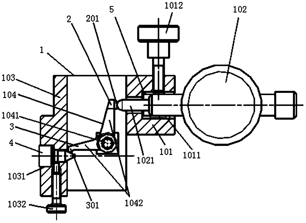
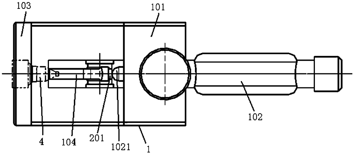
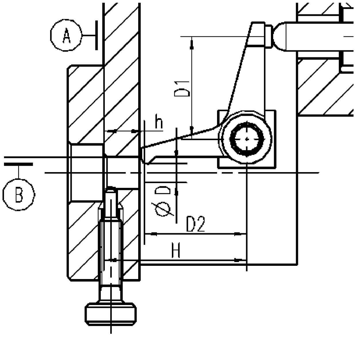
[0030] figure 1 It is a structural schematic diagram of a diameter measuring device for a given section of a fuel nozzle conical part in a preferred embodiment of the present invention; figure 2 yes figure 1 Schematic diagram of the top view structure; image 3 is a schematic structural view of the measuring part of the preferred embodiment of the present invention; Figure 4 It is a schematic structural view of the part to be tested in the preferred embodiment of the present invention.

[0031] Such as figure 1 with figure 2 As shown, the diameter measuring device of a given cross section of the fuel nozzle conical part of the present embodiment includes a meter frame 1, and the meter frame 1 includes a meter mounting part 101 for assembling a meter 102...


PUM


Abstract

The invention discloses a device and method for measuring a diameter of a given cross section of a conical component such as a fuel nuzzle. A device for measuring a diameter of a given cross section of a conical component such as a fuel nuzzle, comprises a gauge frame. The gauge frame comprises a gauge mounting part for mounting a gauge, a gauge mounted inside the gauge mounting part and performing accurate length measurement through the displacement and retract distance of a gauge rod, a component mounting part used for mounting components to be measured, and a lever mechanism arranged between the gauge mounting part and the component mounting part and used for reflecting the diameter of the given cross section of the component to be measured as a length value on the gauge. The diameter of the component is measured by using a comparison method; conversion steps are cancelled; the influence of centering precision on measurement precision is eliminated. The measurement can be carried out during a conical surface manufacturing process and can help measure the product processing state in real time to determine processing parameters. Forced directions are converted through the level mechanism, but measurement values are not influenced; deformation errors resulting from gauge rod elastic bending due to axial force when the gauge rod is directly pushed by the conical surface are avoided.

Description

technical field [0001] The invention relates to the technical field of processing conical parts of fuel nozzles of aero-engines, in particular to a diameter measuring device for a given section of conical parts of fuel nozzles. In addition, the present invention also relates to a method for measuring the diameter of a given section of a fuel nozzle-like conical part comprising the above-mentioned device for measuring the diameter of a given section of the fuel nozzle-like conical part. Background technique [0002] At present, the measurement technology of cone section diameter mainly includes electromagnetic induction technology, optical measurement and indirect measurement by measuring length (such as Figure 5 ) and other methods. Electromagnetic induction technology and optical measuring instruments are expensive, and cannot be measured online, and cannot directly guide production. [0003] By measuring the length ( Figure 5 Middle H) Indirect measurement of the cross-...

Claims


Application Information

Patent Timeline
Patent Type & Authority Patents(China)
IPC IPC(8): G01B5/08
CPCG01B5/08
Inventor 肖俊韩国兴黄志斌盛波
Owner CHINA HANGFA SOUTH IND CO LTD
Learn More