A pull-out test loading device
A loading device and pull-out test technology, which is applied in the test of foundation structure, construction, foundation structure engineering, etc., can solve the problem that the confinement effect of steel pipes on concrete cannot be considered, the accurate measurement of pull-out performance cannot be achieved, and the failure of bonding at the anchorage interface and other issues to achieve the effect of improving feasibility and versatility, saving test costs, and avoiding deformation errors
- Summary
- Abstract
- Description
- Claims
- Application Information
AI Technical Summary
Problems solved by technology
Method used
Image

Examples
Embodiment 1
[0045] In order to overcome the problems existing in the traditional pull-out test device, a pull-out test loading device is provided, which can complete the pull-out test by adding pads and other devices according to different loading requirements. The easy-to-operate pull-out test loading device can complete the pull-out test by adding pads and other devices according to different loading requirements.
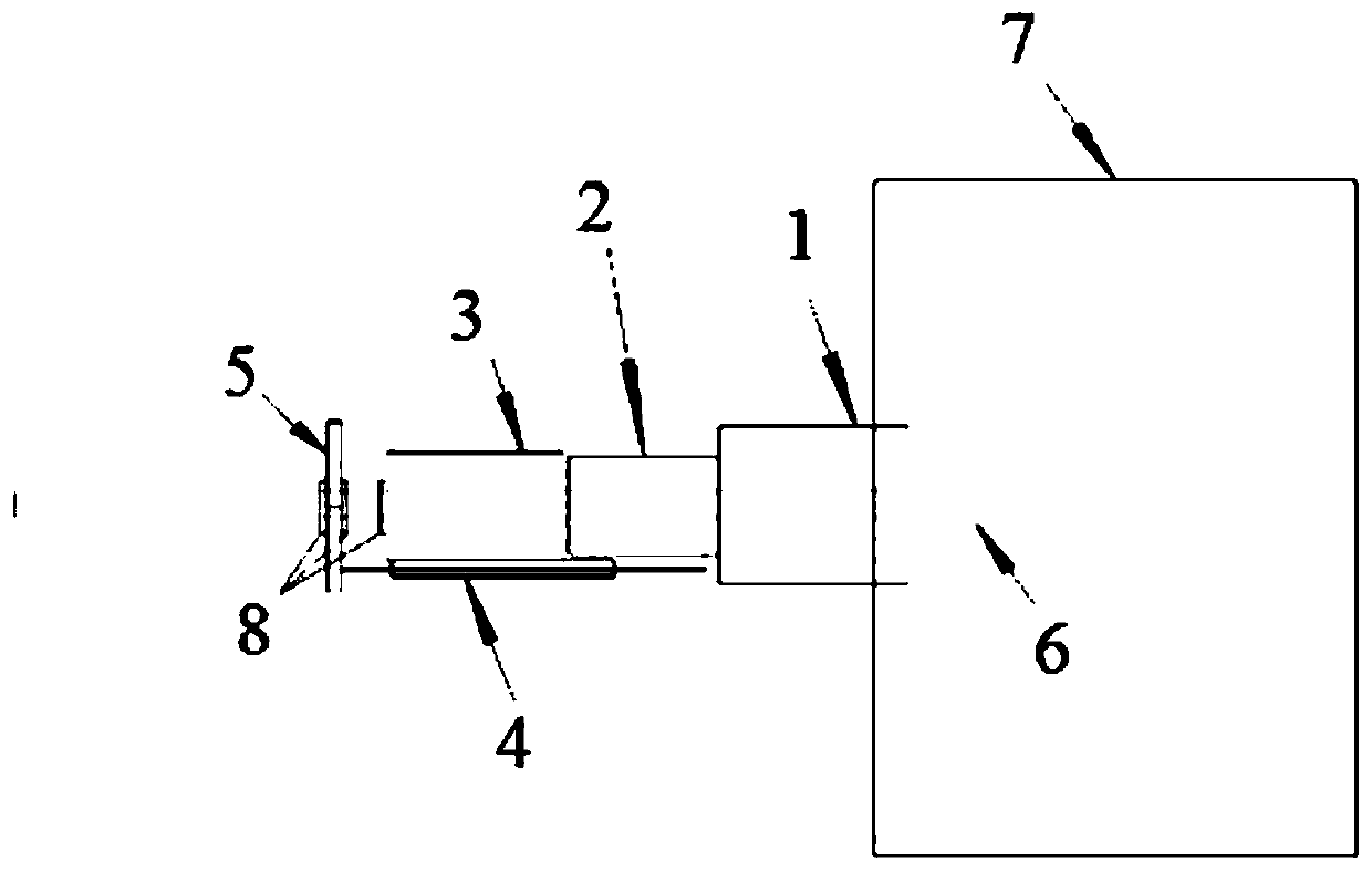
[0046] A kind of drawing test loading device, is set as the single drawing device of the drawing device of single small steel pipe such as figure 1 As shown, it includes a pad 1, a sensor 2, a puller 3, a displacement meter 4, a bracket 5 and a small steel pipe 6, the front end of the small steel pipe 6 is inserted into the steel pipe concrete 7, and the pad 1 passes through the small steel pipe 6 and the steel pipe concrete 7 contacts, fixed on the outer edge of the steel pipe concrete 7, the sensor 2 is fixed on the rear side of the pad 1 through the small steel pipe 6, th...
Embodiment 2
[0056] To the pull-out test loading device of embodiment 1, concrete test process is as follows:
[0057] 1. Pre-embed the small steel pipe in the concrete filled steel pipe, insert the fixed end of the small steel pipe into the large steel pipe of the concrete filled steel pipe before pouring the concrete, and then pour the concrete to form the concrete filled steel pipe.
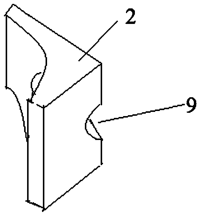
[0058] 2. The cushion block passes through the small steel pipe and penetrates the slot hole, and the curved surface of the cushion block is seamlessly fixed on the outer edge of the steel pipe concrete to ensure that the cushion block fully plays the role of connection.
[0059] 3. The sensor runs through the small steel pipe in the middle, and is connected behind the pad, and the gasket is installed on the small steel pipe behind the pad first, that is, a gasket is added between the pad and the sensor for buffering and protection. .
[0060] 4. The puller passes through the middle through hole, and is c...
Embodiment 3
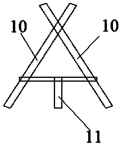
[0066] When measuring the load-displacement curve at different positions of the concrete filled steel tube, multiple pulling devices for small steel tubes can be installed at the same time for testing. A plurality of small steel pipes are arranged in parallel in the vertical direction on the outer edge of the steel pipe of the concrete-filled steel pipe, and installation tests at different positions can also be carried out as required. Through multiple small steel pipes, the superposition effect and group anchor effect of the damaged area can be studied.
[0067] Such as Figure 4 As shown in , three small steel pipes are set in the vertical direction. The three small steel pipes are arranged in parallel on the same straight line. The front ends of the three small steel pipes are all inserted into the steel pipe concrete. The setting of the steel pipe is provided with a spacer 1, a sensor 2, a puller 3, and a displacement gauge 4, and the other two small steel pipes are respe...
PUM
 Abstract
Description
Claims
Application Information
 - R&D
- Intellectual Property
- Life Sciences
- Materials
- Tech Scout
- Unparalleled Data Quality
- Higher Quality Content
- 60% Fewer Hallucinations
Browse by: Latest US Patents, China's latest patents, Technical Efficacy Thesaurus, Application Domain, Technology Topic, Popular Technical Reports.
© 2025 PatSnap. All rights reserved.Legal|Privacy policy|Modern Slavery Act Transparency Statement|Sitemap|About US| Contact US: help@patsnap.com