
Bubble flow guide full-liquid type shell tube evaporator

A flooded, evaporator technology, used in evaporator/condenser, refrigeration and liquefaction, refrigeration components, etc., can solve the problems of blockage of heat exchange tube channels, high reliability requirements, complex structure, etc., to reduce the number of, The effect of improving the overall heat transfer performance and reducing the amount of air bubbles

Active Publication Date: 2016-05-04
SHANGHAI JIAO TONG UNIV +1
View PDF8 Cites 4 Cited by
  • Summary
  • Abstract
  • Description
  • Claims
  • Application Information

AI Technical Summary

Problems solved by technology

However, the device uses an ultrasonic vibrating rod to quickly separate a large number of small bubbles generated on the outer surface of the tube from the wall to prevent the bubbles from converging. These small bubbles may still converge into large bubbles and block the heat exchange tube channel in the upper area, resulting in a decrease in efficiency

Method used


Image

  • Bubble flow guide full-liquid type shell tube evaporator
  • Bubble flow guide full-liquid type shell tube evaporator
  • Bubble flow guide full-liquid type shell tube evaporator

Examples


Embodiment 1

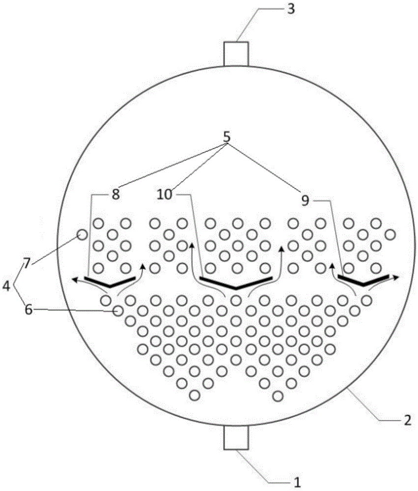
[0021] Such as figure 1 As shown, this embodiment includes: a shell 2, a heat exchange tube 4 and a bubble deflector 5, wherein: the upper part of the shell 2 is provided with a shell-side outlet 3, and the lower part is provided with a shell-side inlet 1. The heat exchange tubes 4 arranged in the casing 2 include: bottom heat exchange tubes 6 and upper layer heat exchange tubes 7 . The air bubble deflector 5 is V-shaped, including: a left V-shaped deflector 8, a right V-shaped deflector 9, and a middle V-shaped deflector 10, which are arranged in rows on the bottom heat exchange tubes 6 in sequence. And between the upper layer heat exchange tube 7.

[0022] The bottom heat exchange tubes 6 are arranged in a conventional tight and equidistant equidistant triangle. In this area, the refrigerant with a certain degree of subcooling enters the shell 2 from the shell side inlet 1, and the temperature of the refrigerant rises from the subcooling temperature to the evaporation temp...

Embodiment 2

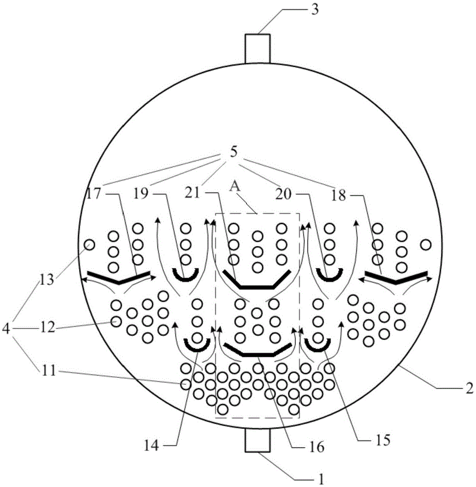
[0026] Such as figure 2 As shown, this embodiment includes: a shell 2, a heat exchange tube 4 and a bubble deflector 5, wherein: the upper part of the shell 2 is provided with a shell-side outlet 3, and the lower part is provided with a shell-side inlet 1.

[0027] The difference between this embodiment and embodiment 1 is:

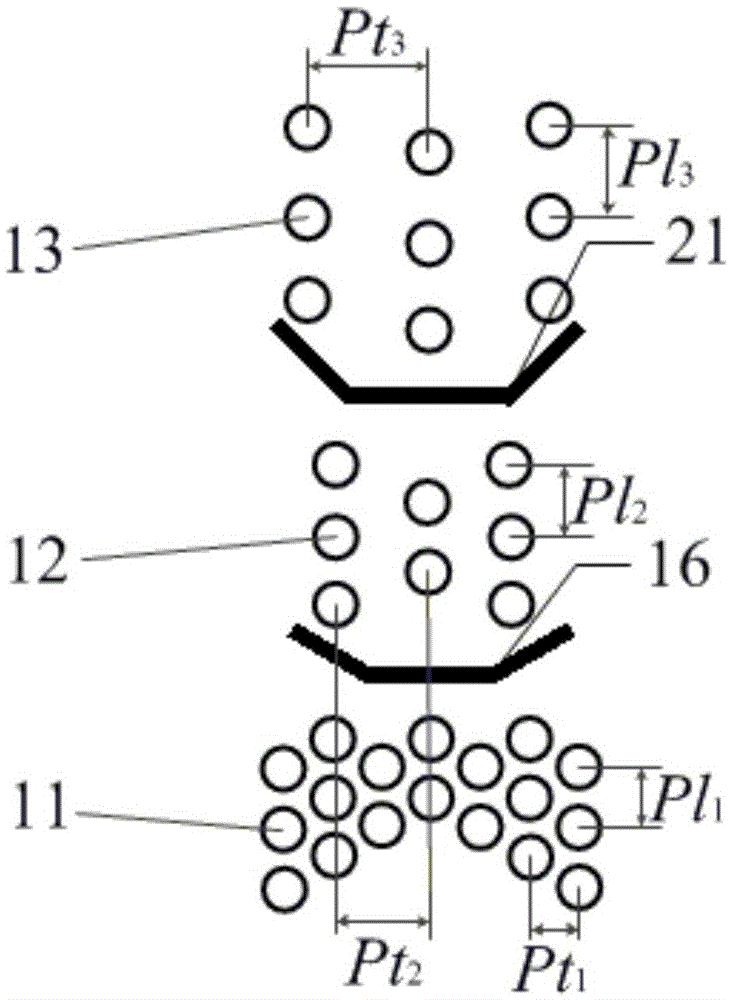
[0028] The heat exchange tube 4 includes: a bottom heat exchange tube 11 , a middle layer heat exchange tube 12 and an upper layer heat exchange tube 13 . Between the bottom heat exchange tubes 11 and the middle heat exchange tubes 12, the lower left U-shaped deflector 14, the lower middle trapezoidal deflector 16, and the lower right U-shaped deflector 15 are arranged in rows in sequence; Between the heat exchange tubes 13 and the middle heat exchange tubes 12, the upper left V-shaped deflector 17, the upper left U-shaped deflector 19, the upper middle trapezoidal deflector 21, and the upper right U-shaped deflector are arranged in rows. The font defl...


PUM


Abstract

A bubble flow guide full-liquid type shell tube evaporator comprises heat exchange tubes and bubble flow guide plates arranged in a shell. The heat exchange tubes are arranged on the upper portions and the lower portions of the bubble flow guide plates; longitudinal air flues are formed on the two sides of the bubble flow guide plates; bubbles are exhausted out of the area where the heat exchange tubes are placed through the air flues; the bubble flow guide plates are in a V shape or a U shape or a trapezoid shape; and the convex faces of the bubble flow guide plates face to the rising direction of the bubbles. The bubble flow guide full-liquid type shell tube evaporator obviously reduces the quantity of the bubbles attached to the heat exchange tubes, prevents the bubbles from forming an air film outside the heat exchange tubes, fully performs the performance of the heat exchange tubes, and improves the overall heat exchange performance of the evaporator.

Description

technical field [0001] The invention relates to a technology in the field of refrigeration and low temperature technology, in particular to a bubble-guided flooded shell-and-tube evaporator. Background technique [0002] Flooded shell-and-tube evaporators are widely used in water chillers, relying on the heat exchange between the hot fluid in the heat exchange tube and the cold fluid outside the tube, so that the fluid outside the tube undergoes a phase change and evaporates into gas, which is discharged out of the evaporator. In the bottom area of ​​the evaporator, part of the heat transferred by the heat exchange tube is used for the sensible heat exchange of the fluid in the supercooled state, and only a small amount of tiny bubbles are generated on the outer surface of the heat exchange tube, which has little influence on the heat exchange performance; In the middle area, the heat transferred by the heat exchange tube is mainly used for latent heat exchange of the fluid ...

Claims


Application Information

Patent Timeline
IPC IPC(8): F25B39/02
Inventor 胡海涛宋强丁国良詹飞龙陈松庄大伟
Owner SHANGHAI JIAO TONG UNIV
Learn More